Elastic wave device

Active Publication Date: 2019-02-28
MURATA MFG CO LTD
View PDF0 Cites 3 Cited by
  • Summary
  • Abstract
  • Description
  • Claims
  • Application Information

AI Technical Summary

Benefits of technology

[0005]Preferred embodiments of the present invention provide elastic wave devices that each include a diamond-b

Problems solved by technology

With such a composite, however, the resulting elastic w

Method used


Image

  • Elastic wave device
  • Elastic wave device
  • Elastic wave device

Examples


Example

[0029]Preferred embodiments of the present invention are described below with reference to the drawings to make the present invention clearly understood.

[0030]It is to be noted that the preferred embodiments set forth herein are illustrative and partial replacement or combination of the structures and configurations between different preferred embodiments is possible.

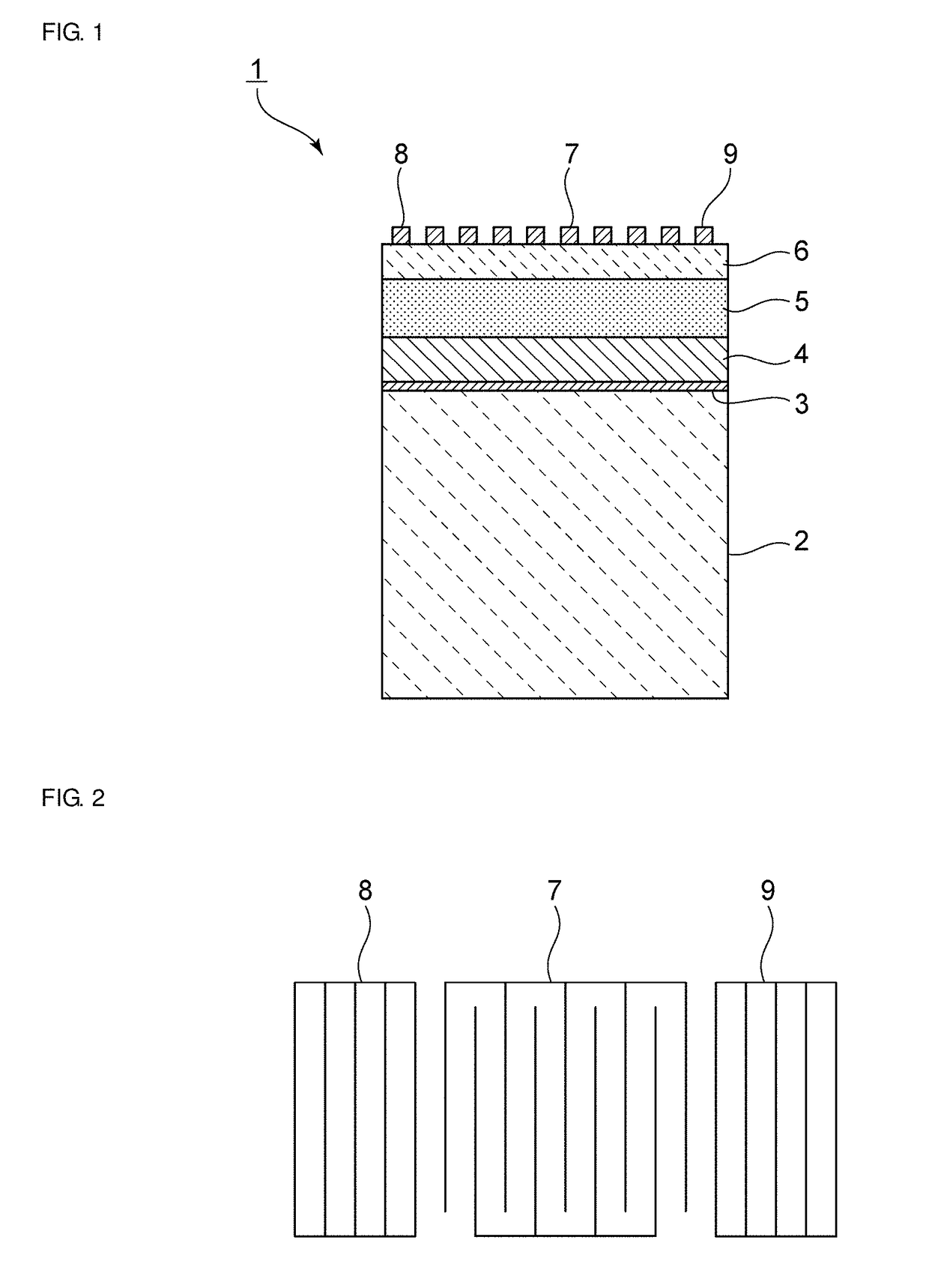
[0031]FIG. 1 is a front cross-sectional view of an elastic wave device according to Preferred Embodiment 1 of the present invention. FIG. 2 is a schematic plan view of the electrode structure of the device.

[0032]The elastic wave device 1 is preferably a one-port surface acoustic wave resonator, for example. The elastic wave device 1 includes a support substrate 2. The support substrate 2 is preferably primarily Si (silicon), for example, although this is not the only possible material and other insulating or semiconductor materials may also be used.

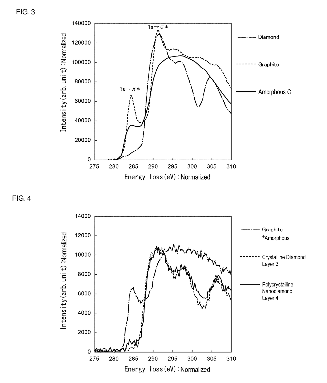
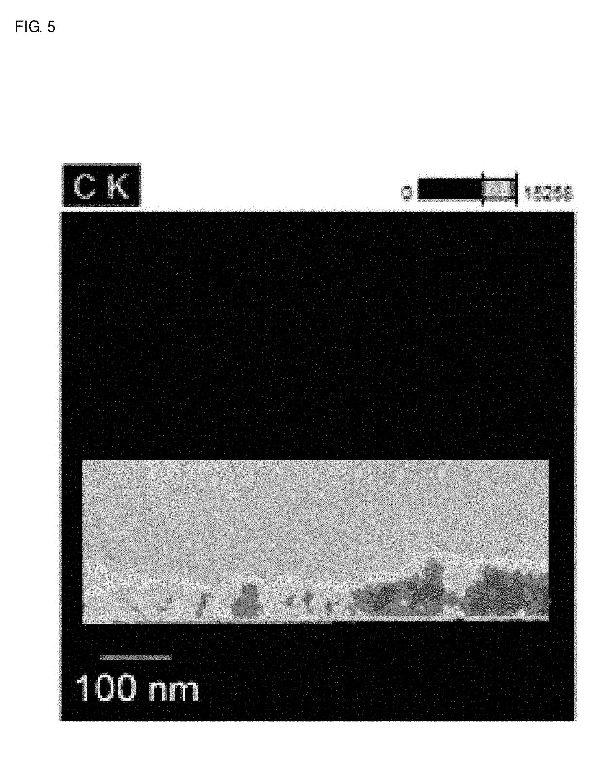
[0033]On the support substrate 2 a crystalline diamond layer 3 and a pol...


PUM


Abstract

An elastic wave device includes a support substrate, a polycrystalline nanodiamond layer provided directly or indirectly on the support substrate, at least one inorganic material layer provided on the polycrystalline nanodiamond layer, a piezoelectric body provided directly or indirectly on the at least one inorganic material layer, and an IDT electrode provided directly or indirectly on the piezoelectric body. The piezoelectric body propagates an elastic wave at a higher velocity than the polycrystalline nanodiamond layer propagates a bulk wave, and at a lower velocity than the at least one inorganic material layer propagates a bulk wave. The polycrystalline nanodiamond layer has a percentage of sp3 bonds of about 50% or more.

Description

CROSS REFERENCE TO RELATED APPLICATIONS[0001]This application claims the benefit of priority to Japanese Patent Application No. 2017-161267 filed on Aug. 24, 2017. The entire contents of this application are hereby incorporated herein by reference.BACKGROUND OF THE INVENTION1. Field of the Invention[0002]The present invention relates to an elastic wave device that includes a piezoelectric body and an interdigital transducer (IDT) electrode stacked on a multilayer body including a support substrate.2. Description of the Related Art[0003]In elastic wave devices, diamond-based materials have been used to reduce propagation loss. For example, in Japanese Unexamined Patent Application Publication No. 2000-203822, a hard carbon film is used that is a composite of graphitic diamond and carbon clusters. A piezoelectric layer is provided on the hard carbon film.[0004]With such a composite, however, the resulting elastic wave device does not have good resonance characteristics.SUMMARY OF THE ...

Claims


Application Information

Patent Timeline
IPC IPC(8): H03H9/05H03H9/02H03H9/145H03H9/25
CPCH03H9/0561H03H9/02559H03H9/02637H03H9/02866H03H9/145H03H9/25H01L41/0477H03H9/02574H03H9/02582H10N30/877
Inventor KIMURA, TETSUYA
Owner MURATA MFG CO LTD
Why Eureka
Try Eureka