Linear motor component mounting apparatus and component inspecting apparatus

a technology for inspecting apparatus and linear motors, which is applied in the direction of electrical equipment, electrical components, dynamo-electric machines, etc., can solve the problems of moving parts preserving gaps, difficult to assemble stators, and it is impossible to pull out the shim after assembling, so as to improve the ease of assembling of linear motors and improve the ease of assembling linear motors

Active Publication Date: 2010-11-18
YAMAHA MOTOR CO LTD
View PDF11 Cites 10 Cited by
  • Summary
  • Abstract
  • Description
  • Claims
  • Application Information

AI Technical Summary

Benefits of technology

[0007]It is an object of the present invention to improve ease of assembles of a linear motor having such a gap accurately and precisely.
[0008]It is another object o

Problems solved by technology

However, in cases where there is a strong magnetic attraction force between a core of an armature and a permanent magnet array of a field element which make up the stator and the mover, it is often difficult to assemble the stator and the mover preserving the

Method used


Image

  • Linear motor component mounting apparatus and component inspecting apparatus
  • Linear motor component mounting apparatus and component inspecting apparatus
  • Linear motor component mounting apparatus and component inspecting apparatus

Examples


Embodiment Construction

[0021]With reference to the drawings, the best mode for carrying out the present invention will now be specifically described.

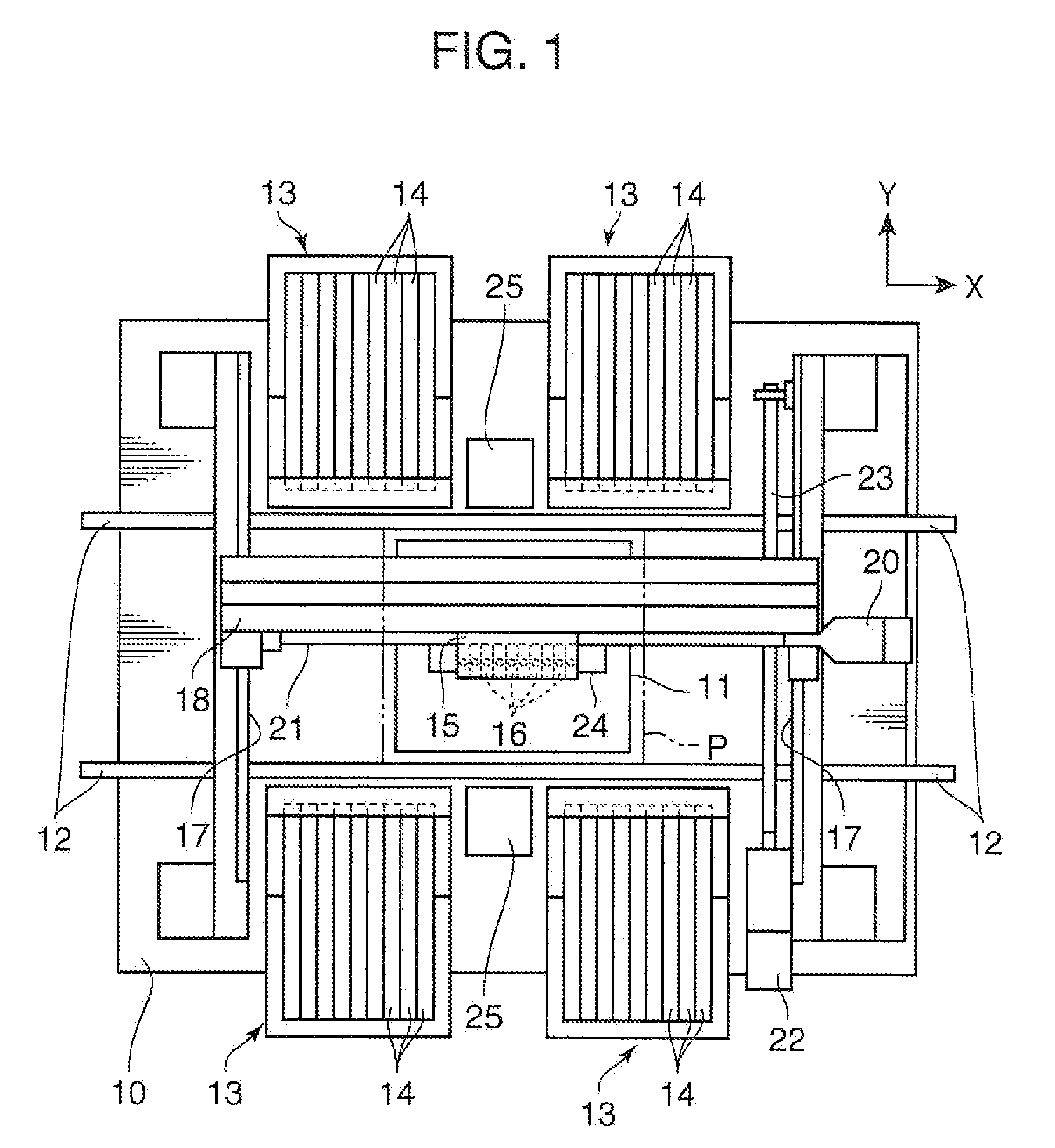
[0022]FIG. 1 is a top plan view showing a schematic structure of a component mounting apparatus using a linear motor according the present invention (a component mounting apparatus according to the present invention). In the figures including FIG. 1 which will be used in the following description, XYZ rectangular coordinate axes are shown in order to clarify a directional relationship in each of the figures.

[0023]As shown in FIG. 1, a conveyer 12 serving as a board carrying mechanism is set up on a base 10 of the component mounting apparatus. The conveyer 12 is adapted to convey a printed-circuit board P (hereinafter referred to simply as “board P”) from a right side to a left side of FIG. 1 to carry the board P in a given operation station (a position of the board P indicated by the two-dot chain line in FIG. 1). A board support unit 11 is disposed in a lowe...


PUM


Abstract

The invention relates to a linear motor equipped with a field element and an armature and adapted to produce a force causing the field element and the armature to be relatively displaced along a given axial direction by interaction of magnetic fluxes generated between the field element and the armature during an operation of supplying electric power to the armature. In one typical aspect of the invention, the linear motor is provided with: a stator which is formed as one of the field element and the armature; a mover which is formed as the other of the field element and the armature; a frame member which defines the axial direction; a rail which is adapted to guide the mover allowing only to reciprocate in a linear direction; a first positioning portion which is provided on the frame member to set a fixing position of the stator with respect to the frame member; and a second positioning portion which is provided on the frame member to set a fixing position of the rail with respect to the frame member in such a manner as to allow the mover to reciprocate along the axial direction with a given gap formed between the mover and the stator positioned by the first positioning portion.

Description

TECHNICAL FIELD[0001]The present invention relates to a linear motor, a component mounting apparatus, and a component inspecting apparatus, and more specifically, to a linear motor suitable for a driving mechanism for driving a component-sucking nozzle up and down, and a component mounting apparatus, and a component inspecting apparatus for driving a component-holding member using the motor.BACKGROUND ART[0002]A linear motor is applied to various industrial machines, including a component mounting apparatus for transferring and mounting an electronic component onto a board. In this component mounting apparatus, a linear motor is used, for example, in a driving mechanism for driving a component-sucking nozzle up and down.[0003]For example, such a linear motor is, as disclosed in a Patent Document 1, provided with a field element having an array of permanent magnets arranged in one direction in such a manner that magnetic poles on the side of surfaces thereof differ from one another, ...

Claims


Application Information

Patent Timeline
IPC IPC(8): H02K41/02
CPCH02K15/16H02K16/00H02K41/031H02K2213/12H05K13/0408H05K13/0452H02K2201/03H05K13/0413H05K13/041
Inventor SAKAI, KIYOTAKAHANAMURA, NAOKI
Owner YAMAHA MOTOR CO LTD
Why Eureka
Try Eureka