Limiting Peak Electrical Power Drawn By Mining Excavators

a technology of mining excavators and peak electrical power, which is applied in the direction of motors/generators/converter stoppers, dynamo-electric converter control, soil-shifting machines/dredgers, etc., can solve the problems of voltage sags and temporary outages in the electrical power distribution network, performance and reliability degradation of applications of interest, and disruption of service to other customers of the electrical power utility company

Active Publication Date: 2010-11-18
SIEMENS IND INC +2
View PDF3 Cites 37 Cited by
  • Summary
  • Abstract
  • Description
  • Claims
  • Application Information

AI Technical Summary

Benefits of technology

[0006]One embodiment of an electrical energy storage unit is an ultracapacitor bank, which may be charged by the electrical power source when the electrical power drawn by the mining excavator is le

Problems solved by technology

Excessive peak power demand may lead to voltage sags and temporary outages in the electrical power distribution network.
Therefore, not only may the performance and reliability of the application of interest be degraded, but also service to other customers of the electrical power utility company may be disrupted.
Electrical mining excavators,

Method used


Image

  • Limiting Peak Electrical Power Drawn By Mining Excavators
  • Limiting Peak Electrical Power Drawn By Mining Excavators
  • Limiting Peak Electrical Power Drawn By Mining Excavators

Examples


Embodiment Construction

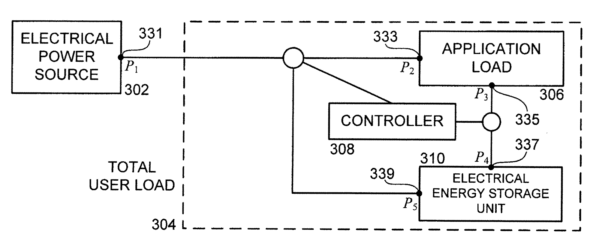
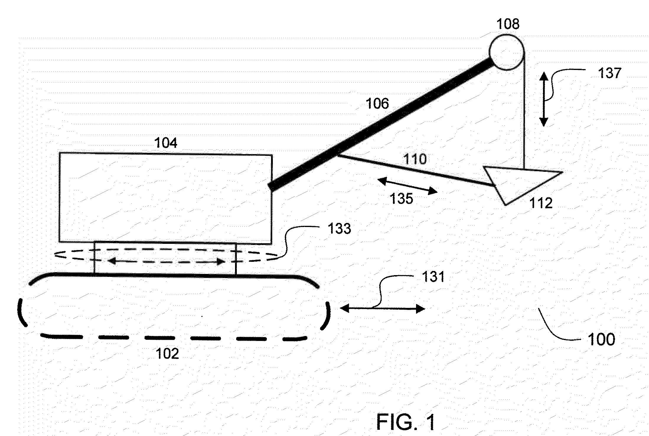
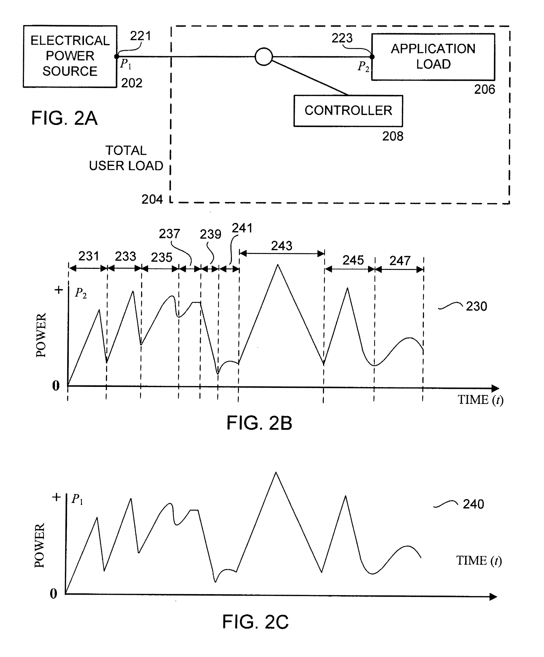
[0026]Mining excavators include electric shovels and draglines. FIG. 1 shows a schematic of an electric shovel 100 to illustrate a mining excavator that consumes significant electrical power. The major components are crawler 102, deck 104, boom 106, hoist 108, handle 110, and dipper 112. Electric motors enable various motions to operate the electric shovel 100. Motion 131 propel (forward / reverse directions) refers to travel of the entire electric shovel 100 with respect to the ground. Motion 133 swing (away / return directions) refers to rotation of deck 104 with respect to crawler 102. Motion 135 crowd (crowd / retract directions) refers to positioning of dipper 112 with respect to boom 106. Motion 137 hoist (hoist / lower directions) refers to positioning dipper 112 up and down with respect to the ground. Multiple electric motors may be used to provide each motion.

[0027]An electric shovel typically performs a series of repetitive operations. For example, it may propel forward near a ban...


PUM


Abstract

The maximum electrical power drawn from an electrical power source by a mining excavator comprising electric motors is reduced by supplying supplementary electrical power from an electrical energy storage unit. The input electrical power drawn by the mining excavator is cyclic. An upper limit is set for the electrical power drawn from the electrical power source. When the input electrical power drawn by the mining excavator exceeds the upper limit, electrical power is supplied by the electrical energy storage unit, such as an ultracapacitor bank. The ultracapacitor bank may be charged by the electrical power source during off-peak intervals. Electrical power generated by electrical motors operating in a regeneration interval may also be recaptured and stored in the electrical energy storage unit.

Description

BACKGROUND OF THE INVENTION[0001]The present invention relates generally to electrical power systems, and particularly to systems for limiting peak electrical power drawn by mining excavators from an electrical power source.[0002]Many applications depend on electricity supplied by an electrical power distribution network, such as the electrical power grid operated by an electrical power utility company. Some commercial and industrial applications draw significant power. Loads are often dynamic, and peak power demand may approach, and, in some instances, exceed, the maximum power available from the electrical power distribution network. Excessive peak power demand may lead to voltage sags and temporary outages in the electrical power distribution network. Therefore, not only may the performance and reliability of the application of interest be degraded, but also service to other customers of the electrical power utility company may be disrupted.[0003]One application which draws signi...

Claims


Application Information

Patent Timeline
IPC IPC(8): H02P7/18
CPCE02F9/2025H02P5/74E02F9/207E02F9/2091
Inventor MAZUMDAR, JOYKOLLNER, WALTERHOLWECK, ANDREASONSAGER, MICHEAL G.PITTIUS, EKKEHARD
Owner SIEMENS IND INC
Why Eureka
Try Eureka