Method and apparatus for rendering a computer generated image

a computer generated image and method technology, applied in the field of methods and apparatus for rendering computer generated images, can solve the problems of expensive identification of a ‘safe’ vertex, i.e., where the produced triangle is entirely inside the original polygon, and achieve the effect of reducing the cost of production

Active Publication Date: 2010-11-18
IMAGINATION TECH LTD
View PDF62 Cites 14 Cited by
  • Summary
  • Abstract
  • Description
  • Claims
  • Application Information

AI Technical Summary

Benefits of technology

[0050]It is also highly desirable to make the colour or texture filling process that occurs once the stencil has been set up, be as efficient as reasonably possible. To this end, the inventor has also appreciated that a single contour arbitrary polygon, without self-intersections, will have an overall winding order and, furthermore, it is usually advantageous for this winding order to be consistent for all objects drawn by an application. (This is due to the ‘triangle fill’ or ‘tie-breaking rules’ of graphics hardware as, say, summarised by the OpenGL, DirectX, or OpenVG standards, to avoid artefacts such as ‘gaps’ appearing between abutting objects). For practical systems, a multiple contour arbitrary polygon will thus also use a consistent overall winding order for the other pieces. (By consistent, it should be noted that contours representing ‘holes’ will have the opposite winding order and that each contour will not, in itself, be self-intersecting.)

Problems solved by technology

Unfortunately, the identification of a ‘safe’ vertex, i.e. where the produced triangle is entirely inside the original polygon is expensive.

Method used


Image

  • Method and apparatus for rendering a computer generated image
  • Method and apparatus for rendering a computer generated image
  • Method and apparatus for rendering a computer generated image

Examples


first embodiment

[0080]For example, the process of step 2 applied to a single contour, to generate triangles (ie for P=3), in accordance with the invention will now be described. It is assumed that the contour has N-sides with vertices numbered from Base to Base+N−1:

StepSize := 1;WHILE( StepSize { / / generate all the triangles with this step sizeJ := 0;WHILE (J { / / Get the other two points that will make / / up this trianglePtB := MIN(J+ StepSize, N−1);PtC := MIN(J + 2*StepSize, N−1); / / if this is a non degenerate triangle...IF(PtB != PtC){ / / output triangle {J, PtB, PtC} relative / / to “base”OutputTriangle(J + Base,PtB + Base,PtC + Base);} / / Move to the next triangle in this setJ := J + 2*StepSize;} / / Double the step sizeStepSize := StepSize * 2;}

[0081]It should be appreciated that this simple algorithm can be realised in hardware by one skilled in the art using a language such as VHDL or Verilog and would require only a small number of components including adders, registers, and comparators.

[0082]FIG. 6 ...

second embodiment

[0087]A second preferred embodiment will now be presented that addresses these additional issues. This second embodiment incorporates the additional feature of a very small stack. Assuming the maximum number of vertices in a contour that will ever be encountered is NMax, then this stack needs at most ┌log2(NMax)┐+1 (ie ceiling(log2(Nmax))+1) entries. For example, if in a given system a contour could have at most 216 vertices, then the stack would have no more than 17 entries.

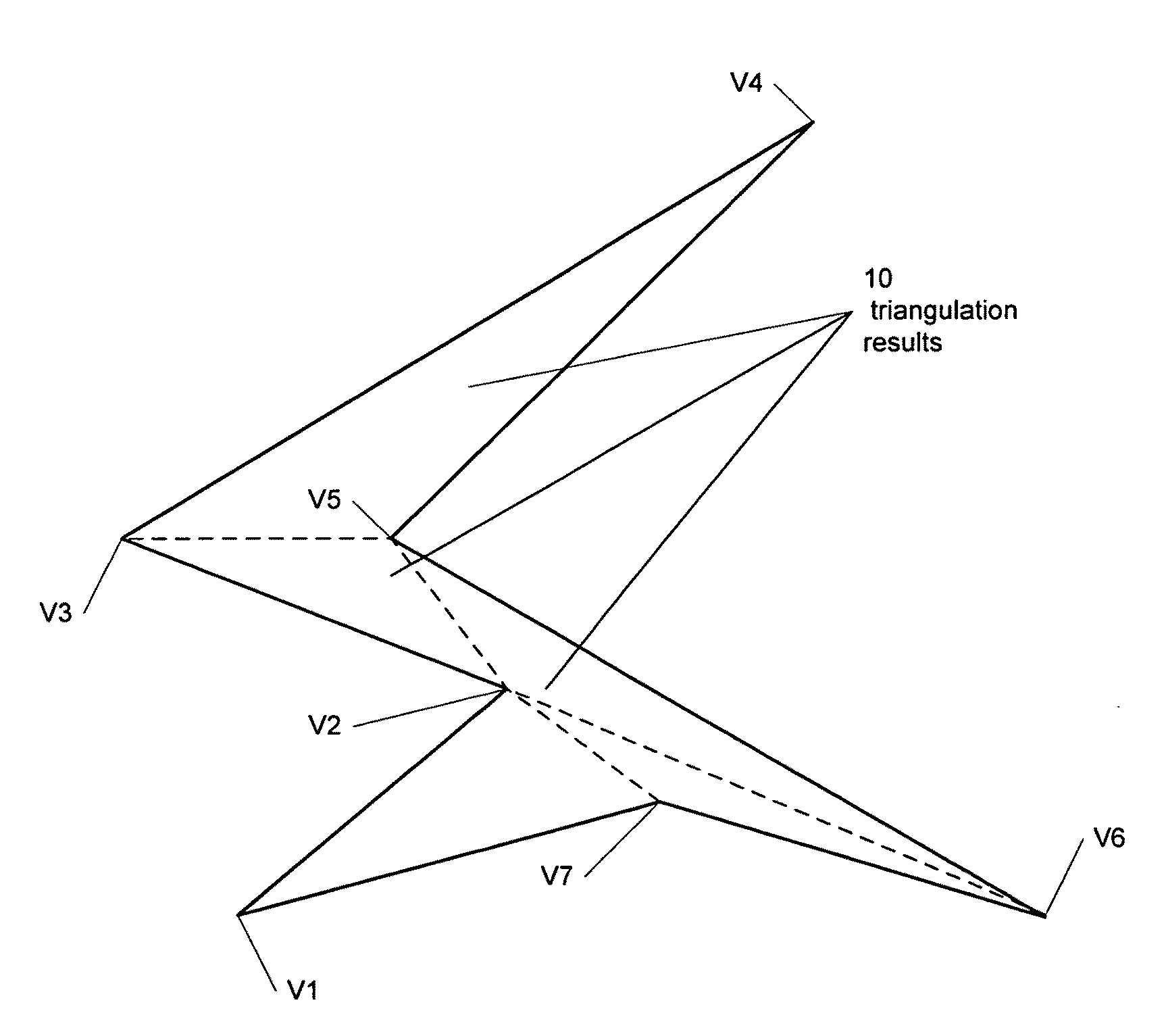
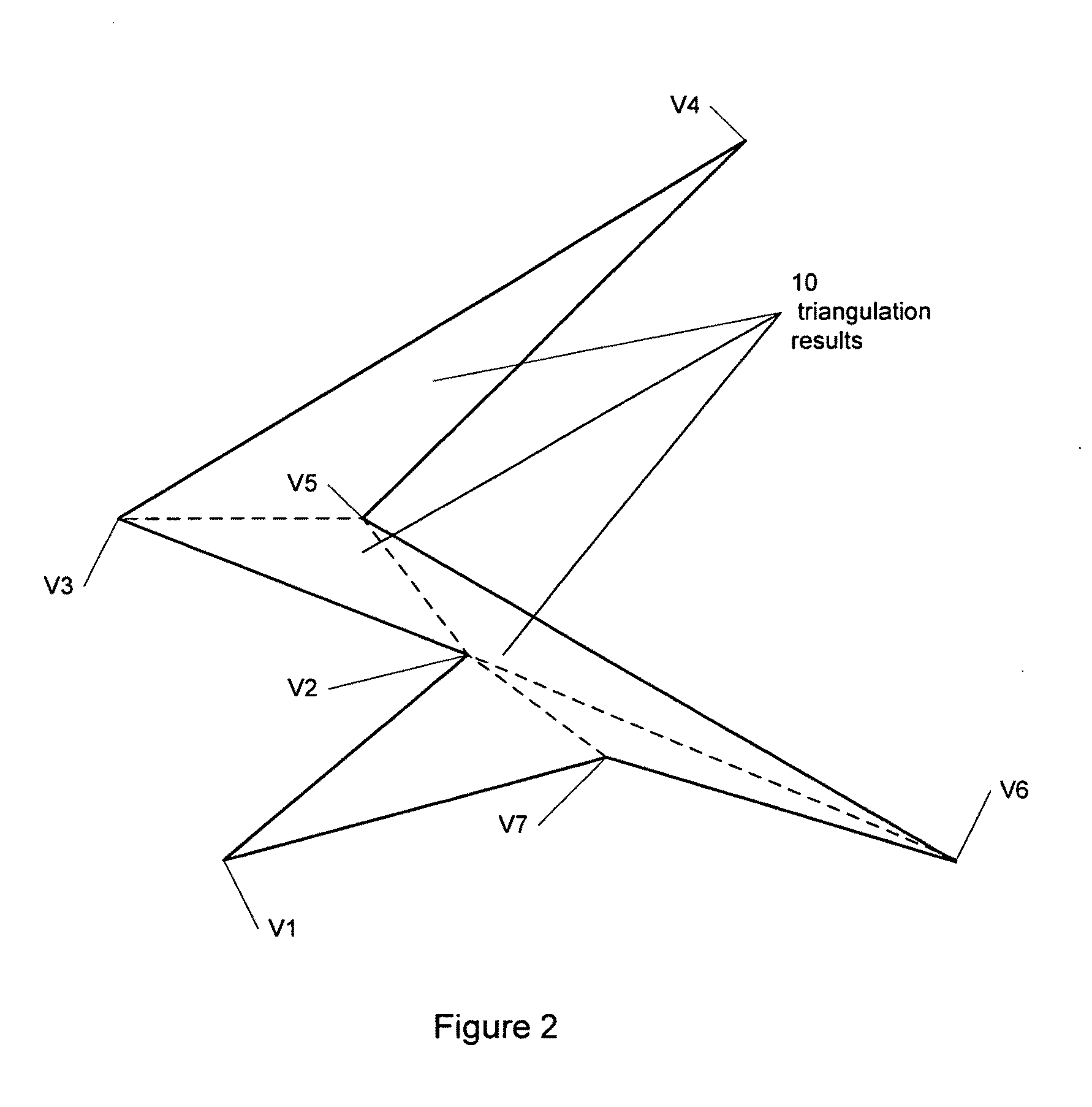
[0088]This embodiment provides interleaving of primitive levels to maximise vertex temporal locality and produces at least one second level primitive before all the first level primitives are produced. Primitive polygon level is reflected in the separation of the vertices of the primitive polygon relative to the vertices of the original arbitrary closed polygonal contour. A first level primitive has vertices which are contiguous vertices in the original closed polygonal contour. Higher level primitives have vert...


PUM


Abstract

A method and apparatus for rendering a computer generated image using a stencil buffer is described. The method divides an arbitrary closed polygonal contour into first and higher level primitives, where first level primitives correspond to contiguous vertices in the arbitrary closed polygonal contour and higher level primitives correspond to the end vertices of consecutive primitives of the immediately preceding primitive level. The method reduces the level of overdraw when rendering the arbitrary polygonal contour using a stencil buffer compared to other image space methods. A method of producing the primitives in an interleaved order, with second and higher level primitives being produced before the final first level primitives of the contour, is described which improves cache hit rate by reusing more vertices between primitives as they are produced.

Description

FIELD OF INVENTION[0001]The invention relates to a method and apparatus for rendering computer generated images, in which the images include at least one closed polygonal contour. Particularly, the invention relates to rendering of images using image space calculations and standard graphics hardware and in which the polygons in the images include ‘arbitrary’ shaped polygons, where ‘arbitrary’ permits the existence concavities, self-intersections, and even multiple ‘contours’.BACKGROUND OF THE INVENTION[0002]In a computer generated image, there are typically a large number of individual polygons. Graphics rendering hardware, in particular 3D graphics hardware, often only has capability for the rendering of triangle primitives or, occasionally, other convex polygons, that is to say, polygons in which all the internal angles of the polygon are less than 180°. Such polygons are relatively straightforward to render. Such specifications include ‘fill rules’ which determine which parts of ...

Claims


Application Information

Patent Timeline
Patent Type & Authority Applications(United States)
IPC IPC(8): G09G5/00G06T15/00
CPCG06T17/20G06T15/005G06T15/00G06T9/00
Inventor FENNEY, SIMON
Owner IMAGINATION TECH LTD
Why Eureka
Try Eureka