Image display apparatus

a technology of image display and display apparatus, which is applied in the field of image display apparatus, can solve the problems of difficult to achieve an image display apparatus capable of presenting images with a wide view angle, low image information presentation efficiency of each display element, and increase the size of the prism disposed near the observer, so as to suppress the generation of images

Active Publication Date: 2010-11-18
CANON KK
View PDF2 Cites 57 Cited by
  • Summary
  • Abstract
  • Description
  • Claims
  • Application Information

AI Technical Summary

Benefits of technology

[0016]The present invention provides a small and thin image display apparatus presenting with a wide view angle an enlarged combined image formed by com

Problems solved by technology

Such a large overlapping area makes image information presentation efficiency of each display element low, which makes it difficult to achieve an image display apparatus capable of presenting images wi

Method used


Image

  • Image display apparatus
  • Image display apparatus
  • Image display apparatus

Examples


embodiment 1

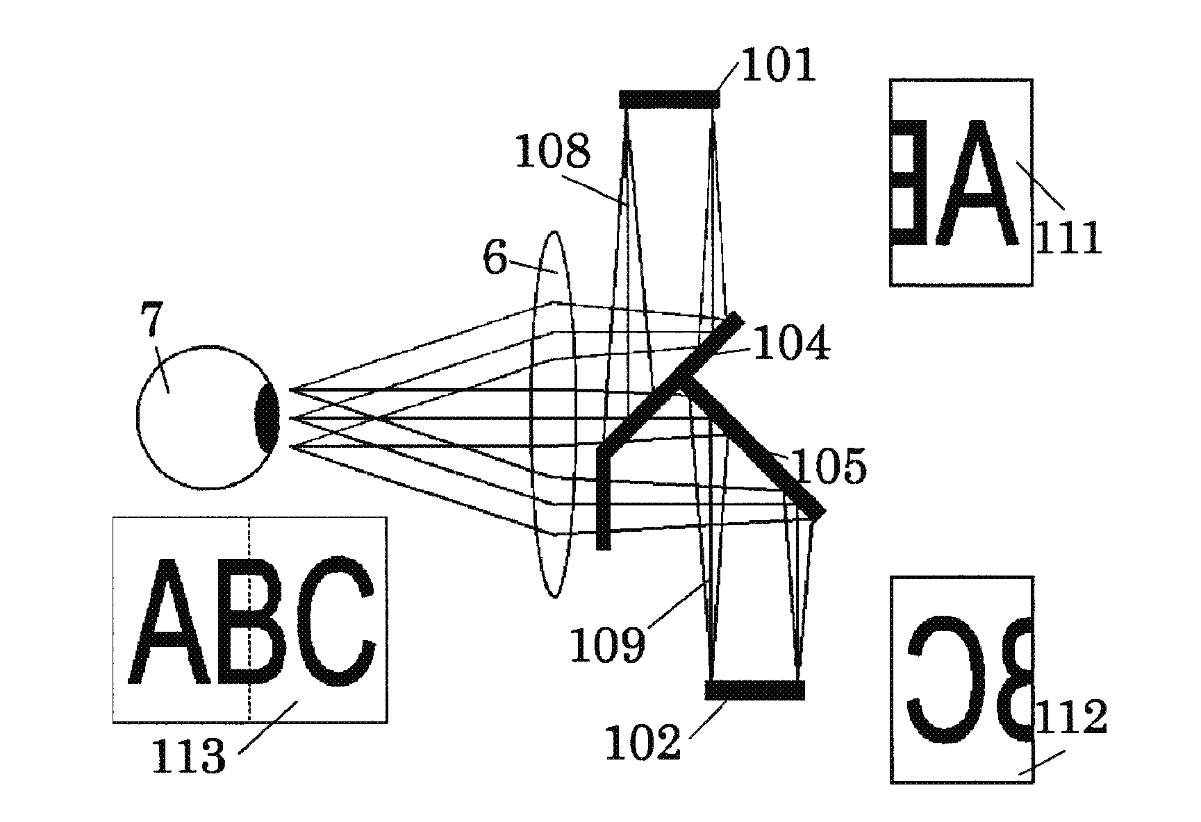
[0042]FIG. 1 shows an HMD (image display apparatus) that is a first embodiment (Embodiment 1) of the present invention. The HMD of this embodiment introduces light fluxes from two display elements provided for two view angles divided in a horizontal direction that is a direction of a decentering cross-section of an optical system to an exit pupil of the optical system. The decentering cross-section of the optical system will be explained later.

[0043]In FIG. 1, reference numeral 101 denotes a first display element, and reference numeral 102 denotes a second display element. As the first and second display elements 101 and 102, a light-emitting display element such as an organic EL (electroluminescence) element or an LCD constituted by a transmissive liquid crystal panel and a backlight unit can be used. The same is applied to other embodiments which will be described later.

[0044]Reference numeral 104 denotes a first optical element, and reference numeral 105 denotes a second optical ...

embodiment 2

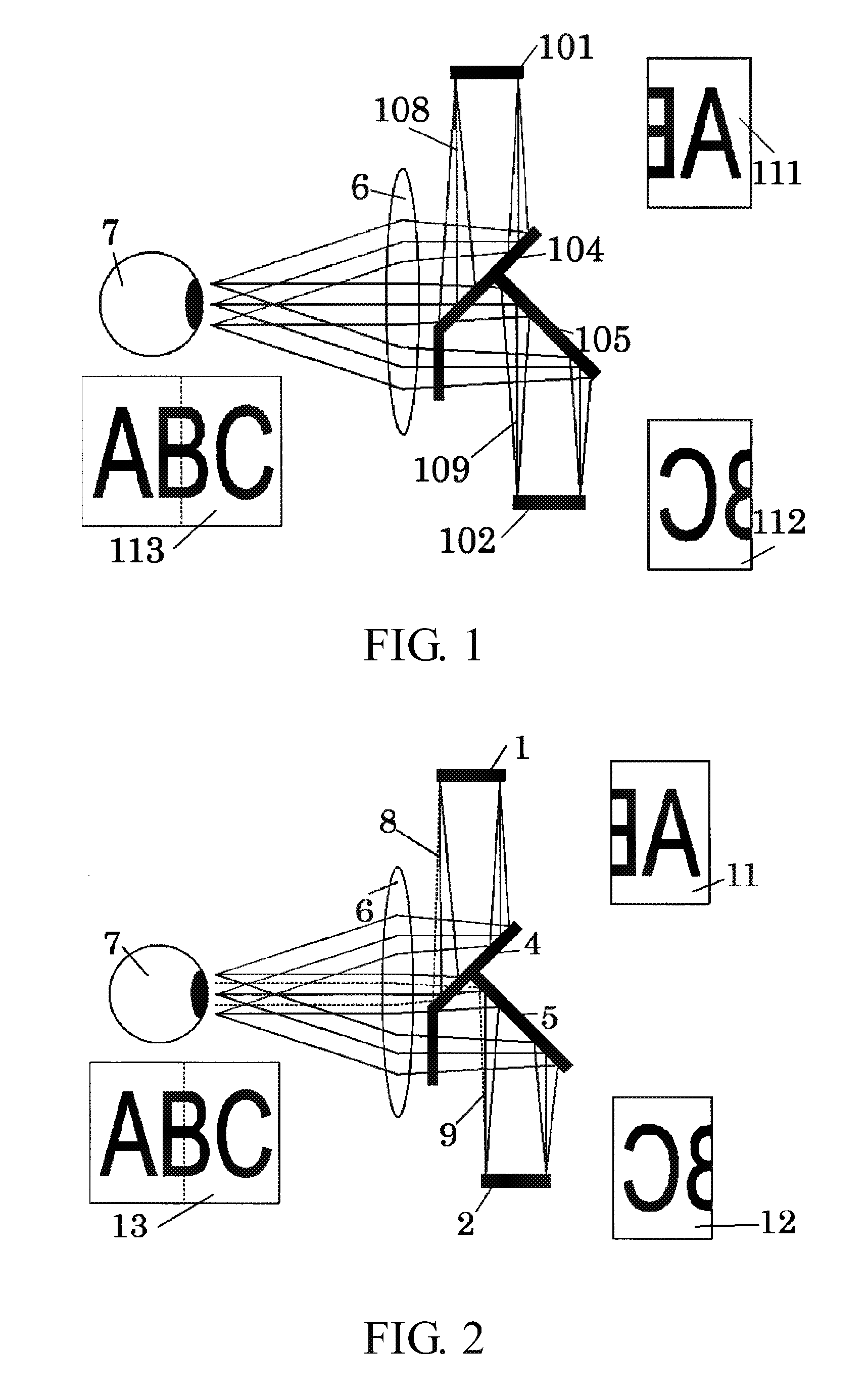
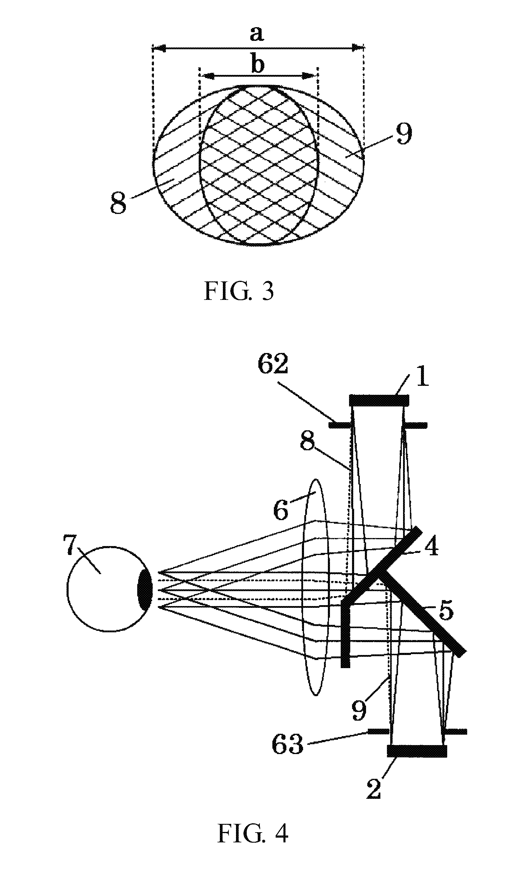
[0057]FIG. 2 shows an HMD (image display apparatus) that is a second embodiment (Embodiment 2) of the present invention. The HMD of this embodiment introduces light fluxes from two display elements provided for two view angles divided in a horizontal direction that is a decentering cross-sectional direction of an optical system to an exit pupil of the optical system.

[0058]In FIG. 2, reference numeral 1 denotes a first display element, and reference numeral 2 denotes a second display element. Reference numeral 4 denotes a first optical element, and reference numeral 5 denotes a second optical element. In this embodiment, a half-mirror is used as the first optical element 4, and a mirror is used as the second optical element 5. Reference numeral 6 denotes an ocular lens. The first and second optical elements 4 and 5 and the ocular lens 6 constitute the optical system. Reference numeral 7 denotes an observer's eye which is placed at a position of the exit pupil of the optical system or...

embodiment 3

[0080]FIG. 7 shows an HMD (image display apparatus) that is a third embodiment (Embodiment 3) of the present invention. The HMD of this embodiment introduces light fluxes from three display elements provided for three view angles divided in a horizontal direction that is a decentering cross-sectional direction of an optical system to an exit pupil of the optical system.

[0081]In FIG. 7, reference numeral 14 denotes a first display element, reference numeral 15 denotes a second display element, and reference numeral 16 denotes the third display element. The second display element 15 and the third display element 16 respectively correspond to “a first display element and “a second display element”. Reference numeral 17 denotes an optical element constituted by a half-mirror, and reference numeral 18 denotes an ocular lens. The optical element 17 and the ocular lens 18 constitute an optical system. Reference numeral 7 denotes an observer's eye which is placed at a position of the exit p...


PUM


Abstract

The image display apparatus includes first and second display elements respectively displaying first and second original images, and an optical system presenting an enlarged combined image of the first and second original images with first and second light fluxes from the first and second display elements. The optical system includes at least one reflective surface. When a cross-section of the optical system on which optical paths of the first and second light fluxes are turned by reflections at the reflective surface is defined as a decentering cross-section, the first and second original images correspond to different view angles in the decentering cross-section. Light flux components respectively included in the first and second light fluxes and introduced to a same image point in the enlarged combined image are overlapped with each other on an exit pupil plane.

Description

BACKGROUND OF THE INVENTION[0001]1. Field of the Invention[0002]The present invention relates to an image display apparatus that combines light fluxes from plural display elements to present one enlarged combined image, in particular, relates to an image display apparatus suitable for a head-mounted display (HMD).[0003]2. Description of the Related Art[0004]For observation optical systems used for image display apparatuses such as HMDs, image presentation with a wide view angle is required to enable natural observation of images and to increase realistic sensation. Moreover, it is desirable that such image display apparatuses being mounted on an observer's head be small and thin.[0005]Some of such small and thin image display apparatuses capable of presenting images with a wide view angle use plural display elements displaying original images for mutually different view angles, and form one image by combining plural enlarged images corresponding to the original images to enable obse...

Claims


Application Information

Patent Timeline
IPC IPC(8): G02B27/01
CPCG02B2027/0123G02B27/0172
Inventor TOHARA, MASAKAZUYAMAZAKI, SHOICHIINOGUCHI, KAZUTAKASAITO, KENICHITSUYUKI, MOTOMI
Owner CANON KK
Why Eureka
Try Eureka