Code converting apparatus, receiver, and code converting method

a code converting and code technology, applied in the direction of electrical devices, instruments, measurement devices, etc., can solve the problems of increasing the amount of calculation and increasing the number of samples, and achieve the effect of less calculation

Inactive Publication Date: 2010-11-18
MITSUBISHI ELECTRIC CORP
View PDF7 Cites 7 Cited by
  • Summary
  • Abstract
  • Description
  • Claims
  • Application Information

AI Technical Summary

Benefits of technology

[0039]A code converting apparatus according to one aspect of the present invention may estimate the incoming time or direction of a received code modulation signal accurately with less calculation by:
[0040]a signal inputting section inputting a first signal sampled in a predetermined sampling cycle from a modulation signal modulated by a spreading sequence composed of m elements in a set A having n kinds of symbols as elements where m≧4d, d≧1, n≧2, and m, d and n are integers;
[0041]a symbol sequence memory section storing a converted sequence of symbols obtained by concatenating consecutive 2d symbols at the center of each of n4d kinds of sequence patterns, each sequence pattern being composed of 4d elements in the set A, the converted sequence of symbols being structured so that d symbol immediately preceding the 2d symbols and d symbol immediately following the 2d symbols are identical to d symbol immediately preceding corresponding 2d symbols and d symbol immediately following the corresponding 2d symbols of a corresponding sequence pattern;
[0042]a symbol sequence specifying section specifying a sequence pattern matching a partial sequence composed of the 2d symbols, the d symbol immediately preceding the 2d symbols and the d symbol immediately following the 2d symbols, among the sequence patterns, for every consecutive 2d symbols included in an input symbol sequence x1 x2 . . . xm obtained by assigning a symbol to the first signal inputted by the signal inputting section in a coding cycle of the spreading sequence;
[0043]a signal generating section generating a pattern signal for each sequence pattern specified by the symbol sequence specifying section for every consecutive 2d symbols included in the input symbol sequence, by adding a partial signal that is a portion to which the 2d symbols are assigned of the first signal inputted by the signal inputting section; and
[0044]a signal converting section generating a second signal by concatenating each pattern signal generated by the signal generating section for each sequence pattern, in an order equivalent to an order of the 2d symbols at the center of each sequence pattern concatenated in the converted sequence of symbols stored in the symbol sequence memory section.

Problems solved by technology

An effective use of despreading in estimating the incoming time or direction of a spread spectrum signal may result in an increase in the number of samples, and lead to an increase in the amount of calculation.

Method used


Image

  • Code converting apparatus, receiver, and code converting method
  • Code converting apparatus, receiver, and code converting method
  • Code converting apparatus, receiver, and code converting method

Examples


embodiment 1

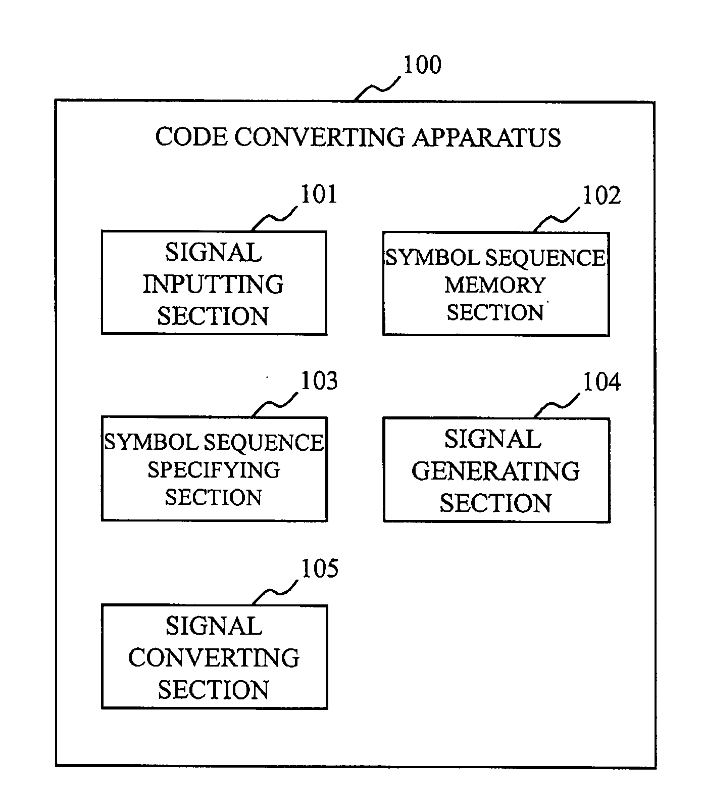
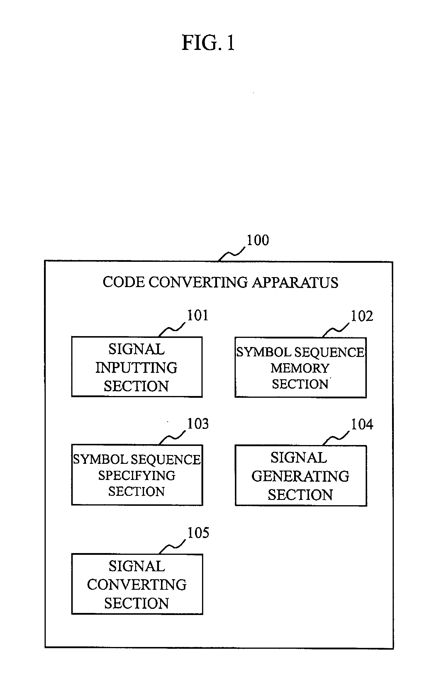
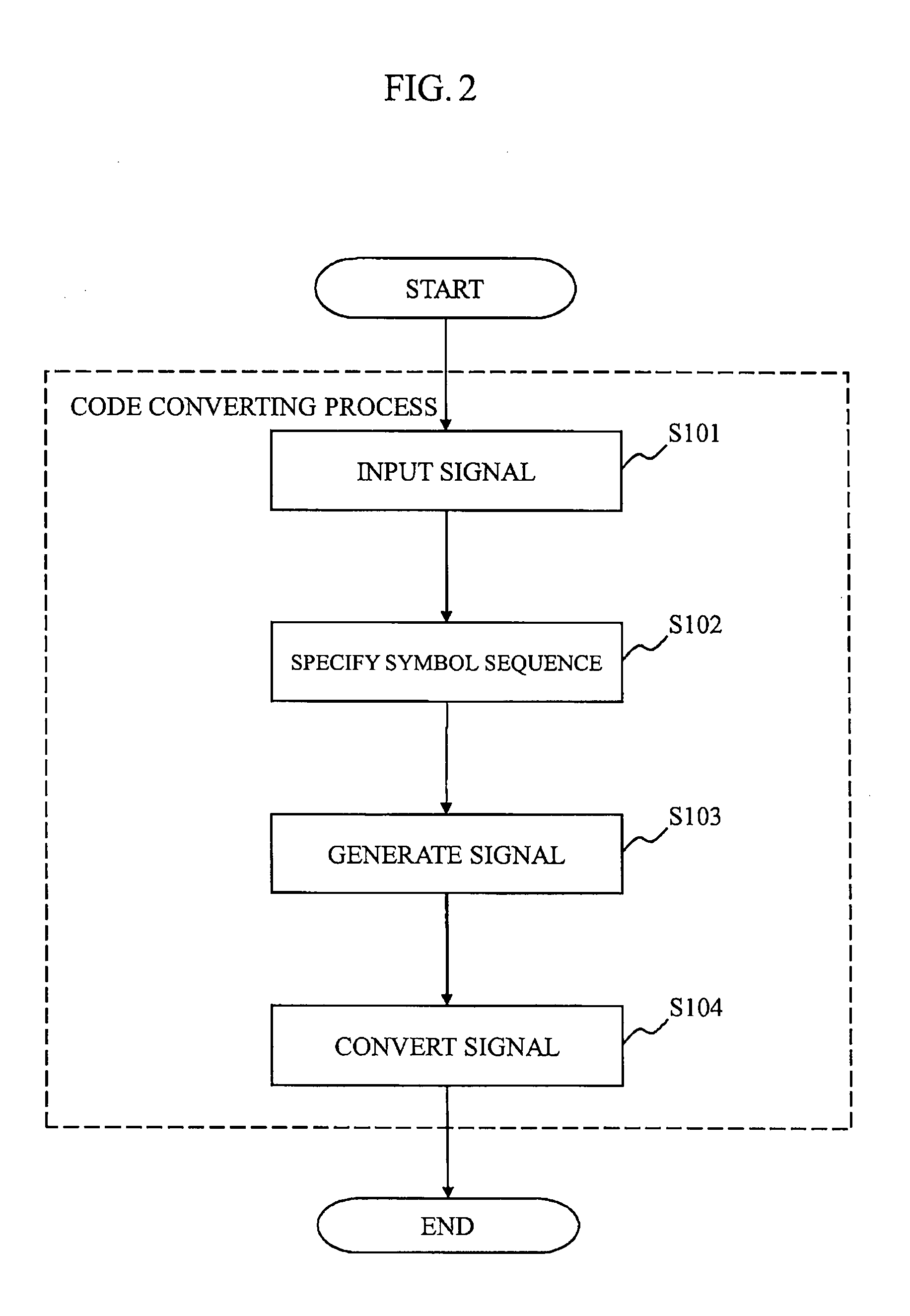
[0046]FIG. 1 shows a block diagram illustrating a configuration of a code converting apparatus 100 according to a first embodiment. FIG. 2 shows a flowchart illustrating an operation of the code converting apparatus 100 (i.e., a code converting method).

[0047]Referring to FIG. 1, the code converting apparatus 100 includes a signal inputting section 101, a symbol sequence memory section 102, a symbol sequence specifying section 103, a signal generating section 104, and a signal converting section 105. Referring to FIG. 2, the code converting apparatus 100 carries out a code conversion process, Step S101 to Step S104, by using the sections shown in FIG. 1.

[0048]The code conversion process of this embodiment uses a symbol sequence x1 x2 . . . xm expressed by a permutation of m elements in a set A having predetermined n kinds of symbols where m, d, and n are integers satisfying m≧4d, d≧1, and n≧2. A symbol sequence composed of consecutive 4d symbols at an arbitrary position in the symbol...

embodiment 2

[0064]In a second embodiment, the code converting method of the first embodiment is applied to a method for estimating multipath in a received signal (hereinafter, referred to also as an “incoming signal” or an “incoming wave”). It is noted that the code converting method of the first embodiment may also be applied to a method for estimating incoming time or direction for a plurality of signals received by an array antenna or the like in the same manner as the second embodiment.

[0065]An example of application of this embodiment to a positioning apparatus using the GPS (Global Positioning System) is described below. It is noted that this embodiment is also applicable to an apparatus using a different communicating method or a different positioning method.

[0066]FIG. 4 shows a block diagram illustrating a configuration of a receiver 200 (i.e., a positioning apparatus using the GPS) according to this embodiment. FIG. 5 shows a block diagram illustrating an example of a hardware configur...

embodiment 3

[0107]The number of appearances of each sequence pattern included in the sequence patterns pi differs. Therefore, by using each sequence pattern an equal number of times, the noise of the code converted signal can be equalized. Thus, in a third embodiment, the signal generating section 104 is designed to add an equal number of partial signals for each sequence pattern in Step S103 in FIG. 2. Specifically, the signal generating section 104 limits the number of times it adds partial signals for each sequence pattern specified by the symbol sequence specifying section 103, to a constant number. The constant number here may be a preset threshold common to all the sequence patterns. Alternatively, the constant number may be the number of times of addition of the partial signal of the sequence pattern having a least number of times of all the sequence patterns.

[0108]Thus, the code converting apparatus 100 of this embodiment may be characterized in that the number of each sequence pattern ...


PUM


Abstract

A code converting apparatus is designed to estimate the incoming time and the like of a signal modulated by a spreading sequence composed of m elements in a set A having n kinds of symbols as elements accurately. A symbol sequence memory section 102 stores a converted sequence of symbols obtained by concatenating consecutive 2d symbols at the center of each sequence pattern pi composed of 4d elements in the set A. The converted sequence of symbols is structured so that d symbol immediately preceding the 2d symbols and d symbol immediately following the 2d symbols are identical to d symbol immediately preceding corresponding 2d symbols and d symbol immediately following the corresponding 2d symbols of a corresponding sequence pattern. A symbol sequence specifying section 103 specifies a matching sequence pattern for every consecutive 2d symbols in a symbol sequence obtained by assigning a symbol to the signal in a coding cycle of the spreading sequence. A signal generating section 104 adds a portion to which the 2d symbols are assigned of the signal. A signal converting section 105 concatenates each pattern signal added for each sequence pattern, in an order equivalent to an order of the 2d symbols at the center of each sequence pattern concatenated in the converted sequence of symbols.

Description

TECHNICAL FIELD[0001]The present invention relates to a code converting apparatus, a receiver, and a code converting method.BACKGROUND ART[0002]An effective use of despreading in estimating the incoming time or direction of a spread spectrum signal may result in an increase in the number of samples, and lead to an increase in the amount of calculation. An example is an estimation of multipath in a GPS (Global Positioning System) signal. U.S. Patent Publication Number 2004 / 0208236, for example, discloses a multipath estimation directed to reduce the number of samples by extracting and analyzing the waveform of a portion of a spreading sequence (i.e., a code) where a symbol changes to an inverted symbol (hereinafter, referred to as a “portion of symbol inversion”), like Vision Correlator (Registered Trademark).DISCLOSURE OF THE INVENTIONProblems to be solved by the Invention[0003]In the conventional art described above, the waveform of a portion of symbol inversion of a spreading sequ...

Claims


Application Information

Patent Timeline
Patent Type & Authority Applications(United States)
IPC IPC(8): H04B1/707G01S19/30H04J13/00H04J13/10
CPCG01S19/30H04J13/107H04B2201/70715H04B1/7075
Inventor NAGANO, TAKAFUMIIWAMOTO, TAKASHI
Owner MITSUBISHI ELECTRIC CORP
Why Eureka
Try Eureka