Long distance multimodal biometric system and method

a biometric and multi-modal technology, applied in the field of biometric identification systems and methods, can solve the problems of inability to scale up the acquisition parameters of finger-print biometrics, inability to accurately match fingerprint biometrics, and inability to meet the needs of users, so as to achieve the effect of fewer constraints and high matching performan

Inactive Publication Date: 2010-11-18
MORPHOTRUST USA
View PDF12 Cites 219 Cited by
  • Summary
  • Abstract
  • Description
  • Claims
  • Application Information

AI Technical Summary

Benefits of technology

[0009]In view of the limitations of the iris acquisition systems described previously, embodiments of the present invention provide a biometric system that is combined with aspects of video surveillance technologies. In particular, embodiments may include an iris acquisition system providing high matching performance and an acquisition process with fewer constraints. Additionally, these embodiments may provide large

Problems solved by technology

A criticism of existing biometric technologies has been that biometric acquisition procedures are often cumbersome and intrusive.
As such, finger-print biometrics is generally not scalable in terms of acquisition parameters, such as stand-off distance and capture volume.
However, facial biometrics is less accurate than other techniques, such as fingerprint biometrics.
Iris biometrics, however, has not yet become ubiquitous as compared to biometrics based on the face or finger-prints.
However, due to the smaller dimensions of the iris, acquisition of iris biometrics from a distance imposes more design challenges than the acquisition of facial biometrics at a distance.
Secondly, the dimensions of the iris are such that iris recognition technologies require signification pixel and spatial resolutions in order to encapsulate enough biometric data.
Commercially available iris acquisition systems meet illumination and resolution requirements by imposing significant constraints on subjects during acquisition.
Constraints imposed on parameters such as stand-off distance, capture volume, and subject motion account

Method used


Image

  • Long distance multimodal biometric system and method
  • Long distance multimodal biometric system and method
  • Long distance multimodal biometric system and method

Examples


Embodiment Construction

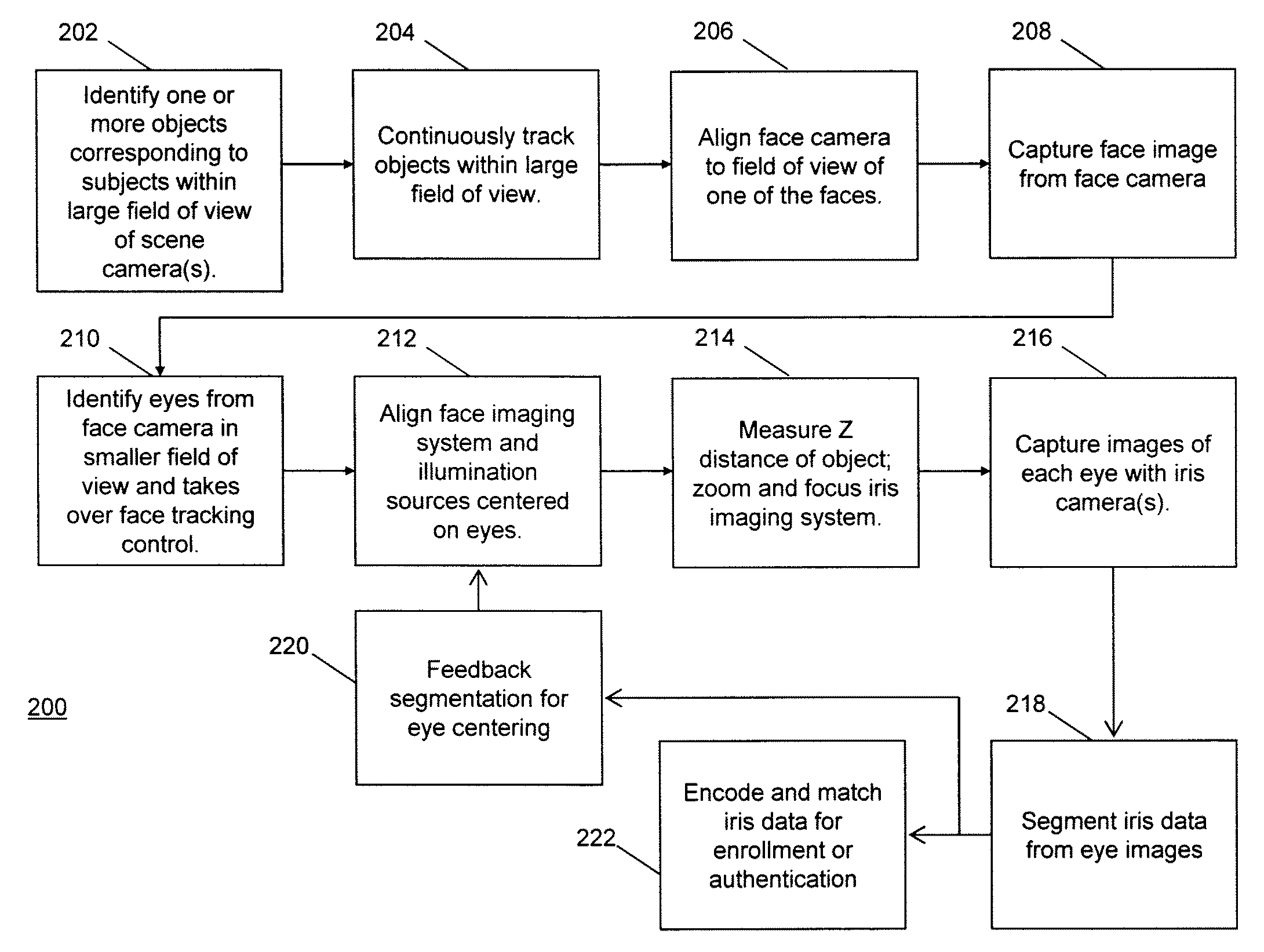
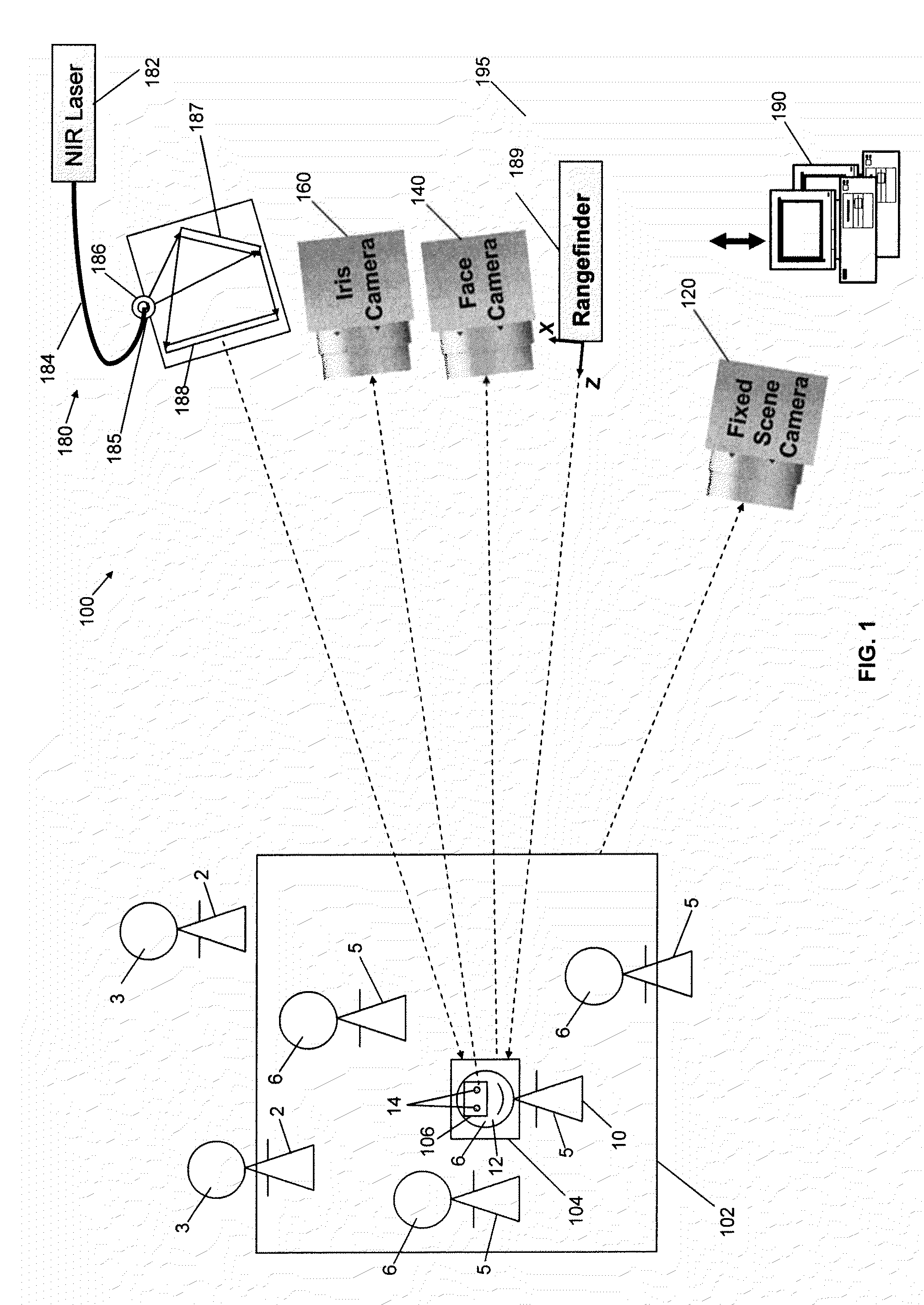
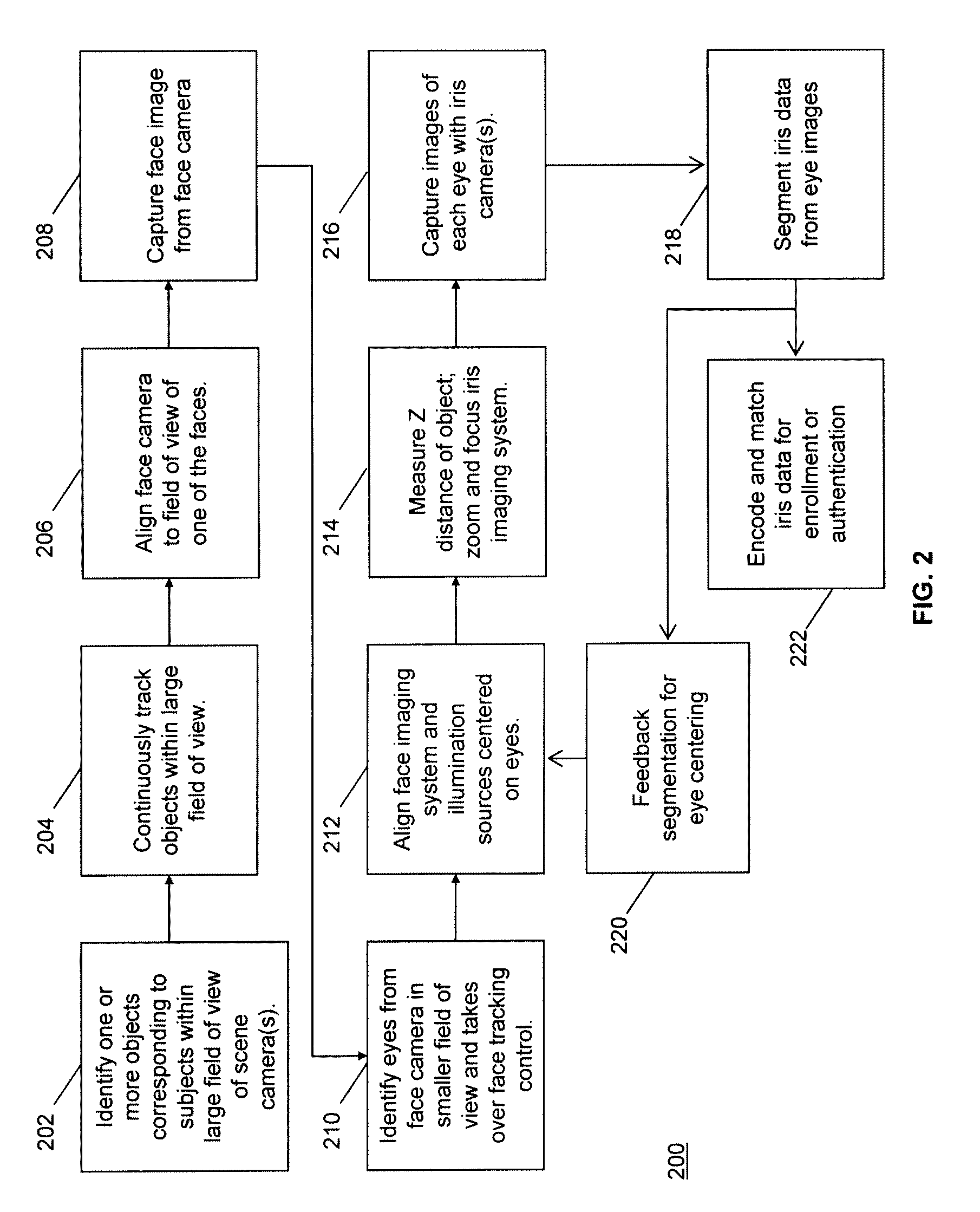
[0032]Referring to FIG. 1, an embodiment of a biometric system 100 employing more than one modality is illustrated. In particular, the multimodal biometric system 100 includes three imaging systems. The first imaging system is a scene imaging system 120 for identifying one or more subjects for biometric identification from a distance. The second imaging system is a face imaging system 140 for capturing images of the face 12 of a target subject 10 from a distance. The third imaging system is an iris imaging system 160 for capturing images of each iris 14 of the target subject 10 from a distance. In some embodiments, the imaging systems 120, 140, and 160 as well as other components may be housed in a single image capture device, but the components of the biometric system 100 may house the components in any number of combinations and any number of devices.

[0033]The scene imaging system 120 may include one or more cameras that capture images based on photons with visible, near-infrared ...


PUM


Abstract

A system for multimodal biometric identification has a first imaging system that detects one or more subjects in a first field of view, including a targeted subject having a first biometric characteristic and a second biometric characteristic; a second imaging system that captures a first image of the first biometric characteristic according to first photons, where the first biometric characteristic is positioned in a second field of view smaller than the first field of view, and the first image includes first data for biometric identification; a third imaging system that captures a second image of the second biometric characteristic according to second photons, where the second biometric characteristic is positioned in a third field of view which is smaller than the first and second fields of view, and the second image includes second data for biometric identification. At least one active illumination source emits the second photons.

Description

CROSS REFERENCE TO RELATED APPLICATIONS[0001]This application is a Continuation-In-Part (CIP) Application of U.S. application Ser. No. 11 / 898,188, filed Sep. 10, 2007, which claims priority to U.S. Provisional Application No. 60 / 844,644 filed Sep. 15, 2006, and claims priority to U.S. Provisional Application No. 60 / 935,973, filed Sep. 10, 2007, U.S. Provisional Application No. 60 / 935,971, filed Sep. 10, 2007, U.S. Provisional Application No. 60 / 987,925, filed Nov. 14, 2007, and U.S. Provisional Application No. 61 / 035,879, filed Mar. 12, 2008, the contents of these applications being incorporated herein by reference.BACKGROUND OF INVENTION[0002]1. Field of Invention[0003]The present invention relates generally to systems and methods for biometric identification, and more particularly, to imaging systems and methods capable of biometric identification according to more than one modality, especially for subjects positioned at a long distance from the image capture system.[0004]2. Descr...

Claims


Application Information

Patent Timeline
IPC IPC(8): G06K9/00H04N7/18
CPCG06K9/00604G06K9/00255G06V40/166G06V40/19
Inventor FRIEDMAN, MARC D.ACCOMANDO, NICHOLAS A.BASHIR, FAISALCASAVERDE, PABLODALY, STEPHEN F.HITCHCOCK, DAVID J.JOSE, ROMINA MARIE JOHNSONMCNERNEY, TIMMULLER, DAVIDRUZHITSKY, VLADIMIRTOSA, YASUNARIUSHER, DAVID
Owner MORPHOTRUST USA
Why Eureka
Try Eureka