Fixing device and image forming apparatus
a technology of fixing device and fixing plate, which is applied in the direction of electrographic process apparatus, instruments, optics, etc., can solve the problems of ineffective reduction of sliding friction between the fixing belt, pressure pad, and low friction sheet b>64/b>, so as to prevent wrinkles, prevent damage to low friction sheet, and long-term stability of low friction sheet
- Summary
- Abstract
- Description
- Claims
- Application Information
AI Technical Summary
Benefits of technology
Problems solved by technology
Method used
Image
Examples
modification example 1
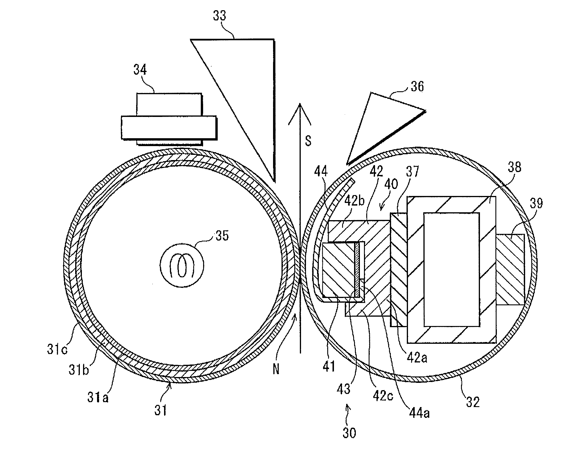
[0091]The structure of the pressing member 40 pertaining to the present invention is not limited to that of the embodiment described above. For example, as FIG. 7 shows, the whole surface of the part of the low friction sheet 44 that is sandwiched between the reinforcing part 43 and the main supporting structure 42a of the rigid pressing part 42 may be bonded to the reinforcing part 43 with a bonding member such as a fluorine-resin-based adhesive agent and a double-faced adhesive tape, or by welding.
[0092]With such a structure, the upstream end 44a, sandwiched between the reinforcing part 43 and the main supporting structure 42a, has an increased resisting force against the pulling force applied to the low friction sheet 44, because of the adherence to the reinforcing part 43. This realizes more stably holding of the upstream end 44a of the low friction sheet 44, and more surely prevents the upstream end 44a from slipping out from between the reinforcing part 43 and the main support...
modification example 2
[0093]Moreover, as shown in FIG. 8, the reinforcing part 43 may be provided with an uneven surface 43b having asperities and facing the main supporting structure 42a, and at the same time, the whole supporting face 42d may have asperities. The asperities on the supporting face 42d can be generated by mechanical polishing, chemical polishing, chemical mechanical polishing, or the like. With such a structure, the upstream end 44a has an increased friction resistance against the pulling force applied to the low friction sheet 44. This realizes more stably holding of the upstream end 44a of the low friction sheet 44, and more surely prevents the upstream end 44a from slipping out from between the reinforcing part 43 and the main supporting structure 42a. Note that instead of providing asperities on both the reinforcing part 43 and the main supporting structure 42a, it is possible to realize such an effect in another manner. For example, asperities may be provided on either one of the re...
modification example 3
[0094]Furthermore, as shown in FIG. 9, a high friction sheet 47 composed of a silicone-based rubber and the like, which have a higher friction coefficient that the low friction sheet 44, may be provided on the surface of the reinforcing part 43 that faces the main supporting structure 42a.
[0095]Such a structure also realizes more stably holding of the upstream end 44a of the low friction sheet 44, and more surely prevents the upstream end 44a from slipping out from between the reinforcing part 43 and the main supporting structure 42a. Note that the high friction sheet 47 may be provided on the main supporting structure 42a. Also, it may be provided on both the reinforcing part 43 and the main supporting structure 42a.
Modification Example of the Image Forming Apparatus
[0096]Image forming apparatuses to which the fixing device pertaining to the present invention can be applied are not limited to monochrome printers as described above as an embodiment. The fixing device is applicable...
PUM
 Abstract
Description
Claims
Application Information
 - R&D
- Intellectual Property
- Life Sciences
- Materials
- Tech Scout
- Unparalleled Data Quality
- Higher Quality Content
- 60% Fewer Hallucinations
Browse by: Latest US Patents, China's latest patents, Technical Efficacy Thesaurus, Application Domain, Technology Topic, Popular Technical Reports.
© 2025 PatSnap. All rights reserved.Legal|Privacy policy|Modern Slavery Act Transparency Statement|Sitemap|About US| Contact US: help@patsnap.com


