
Coupling assembly for furniture components

a technology of furniture components and couplings, which is applied in couplings, dismountable cabinets, manufacturing tools, etc., can solve the problems of limited coupling assemblies employing tongue and groove configurations with enlarged terminal portions, and achieve the effect of ensuring an aesthetically pleasing appearance of the overall furniture item

Inactive Publication Date: 2010-11-18
SAUDER WOODWORKING COMPANY
View PDF6 Cites 41 Cited by
  • Summary
  • Abstract
  • Description
  • Claims
  • Application Information

AI Technical Summary

Benefits of technology

[0011]In accordance with the invention, a tongue and groove assembly can be provided in which the tongue and groove are terminated at a point such that neither exits the end of the respective furniture component member to which the tongue or groove is associated. Accordingly, the edges of the furniture members may be profiled, with the tongue and groove assembly essentially “hidden” from view. Proper member alignment may also be achieved. In this regard, and in accordance with certain aspects of the invention, proper registration of the furniture members is provided by limiting the travel of the tongue within the groove slot. The terminal point of the tongue may engage the terminal point of the groove, with such registration aiding in the proper assembly by consumer, and so as to ensure an aesthetically pleasing appearance for the overall furniture item.
[0015]In addition, a further object of the present invention is to allow the front edges of the members to be profiled, finished, or otherwise decorated. Another object of the invention is to provide a coupling method which maintains proper alignment between the members of a furniture assembly.

Problems solved by technology

To date, coupling assemblies employing a tongue and groove configuration with an enlarged terminal portion have been limited to assemblies where it would be acceptable for the tongue and groove to show on both ends of the assembly.

Method used


Image

  • Coupling assembly for furniture components
  • Coupling assembly for furniture components
  • Coupling assembly for furniture components

Examples


Embodiment Construction

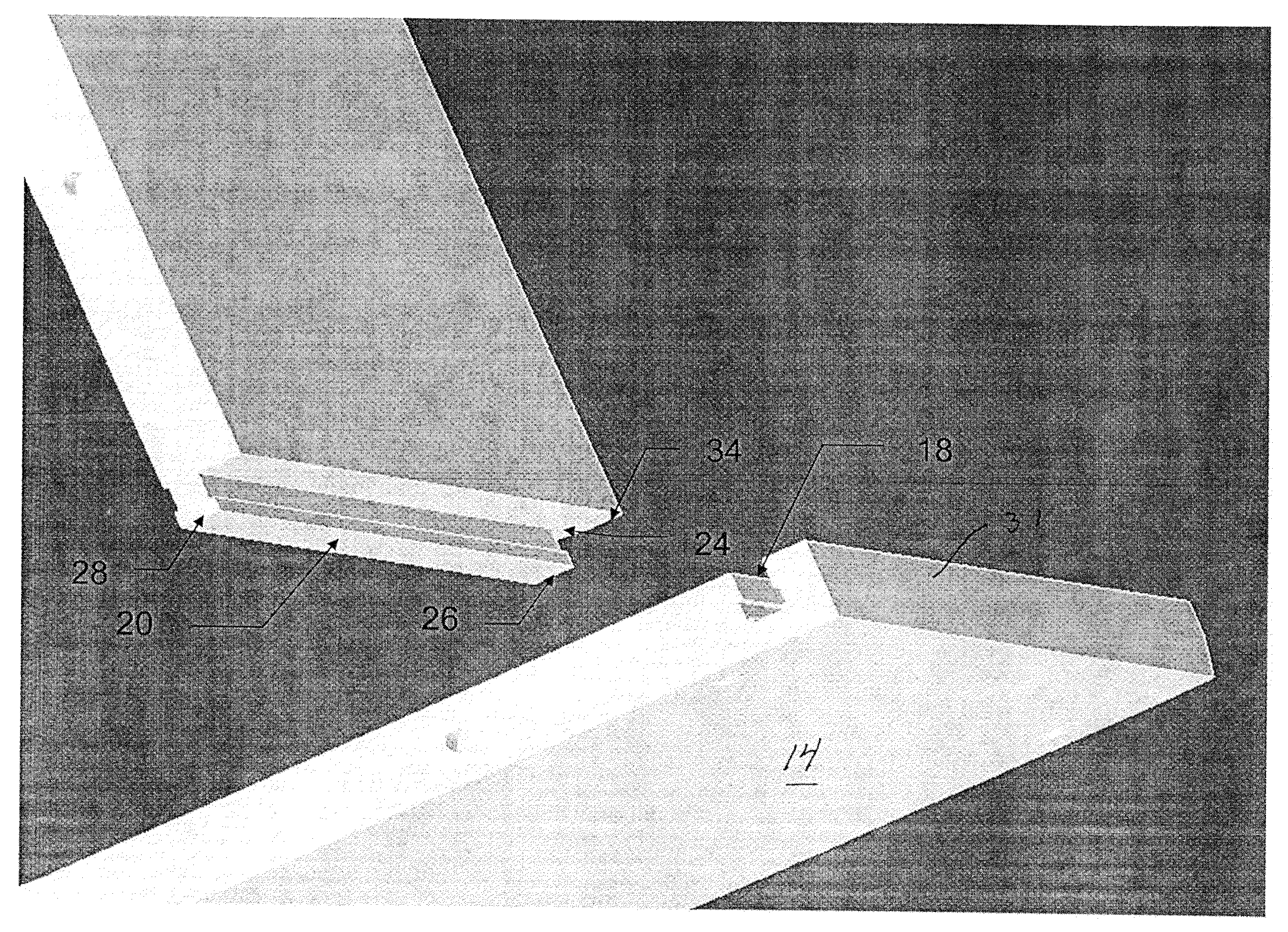
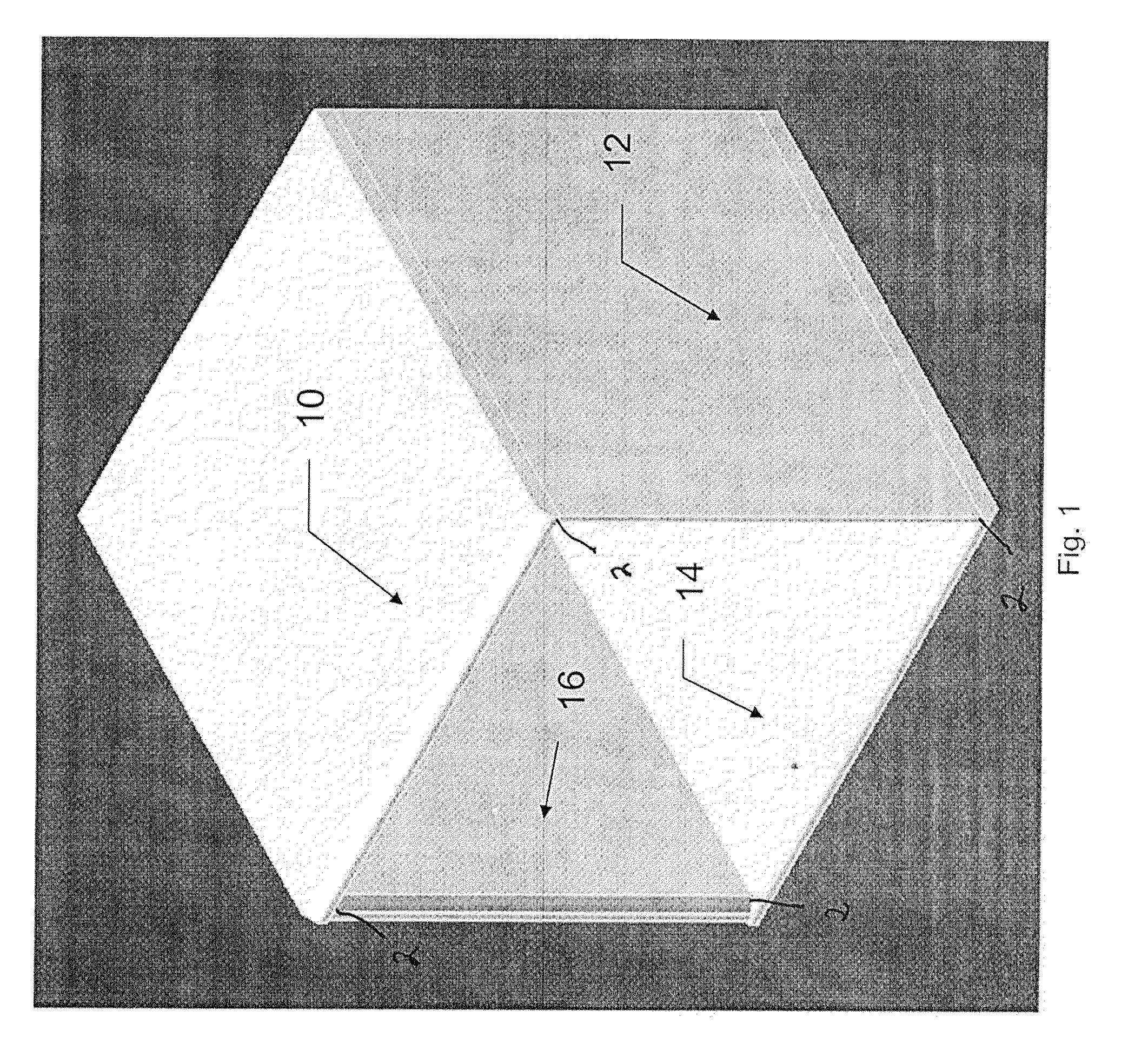
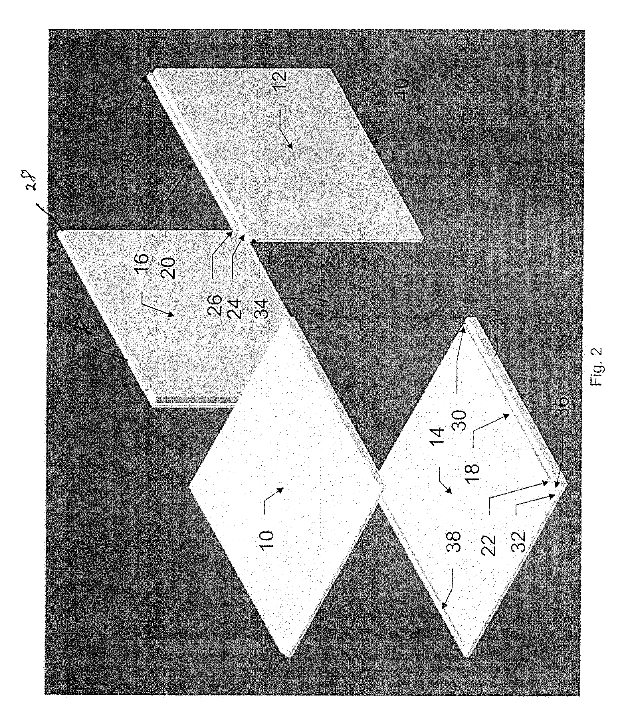
[0024]The principles of the present invention will now be described with respect to a storage cube assembly 1, utilizing coupling assemblies in accordance with the invention and illustrated in FIGS. 1-7. As will be apparent from the subsequent disclosure, the storage cube assembly 1 utilizes coupling assemblies having tongue and groove configurations which terminate at points such that neither the tongue nor the groove exit an end of the respective furniture component members to which the tongue or groove is associated. Advantageously, this feature permits profiling of the edges of the furniture members, in that the tongue and groove configurations are essentially “hidden” from view. Further, the coupling assembly configurations in accordance with the invention still permit proper member alignment.

[0025]Turning to the drawings, and first with respect to FIG. 1, coupling assemblies in accordance with the invention will be illustrated and described with respect to the illustrative emb...


PUM

PropertyMeasurementUnit
Lengthaaaaaaaaaa
Distanceaaaaaaaaaa

Abstract

Coupling assemblies (2) are utilized to assemble a storage cube (1) having a top member (10), right member (12), bottom member (14) and left member (16). Adjacent members are coupled together through the use of T-tongues (20, 40, 44, 48) received within corresponding ones of T-slots (18, 38, 42, 46). The T-tongues and T-slots terminate certain distances (24, 36) from edges of the members (10, 12, 14, 16) thereby providing for blind configurations allowing for edges of members (10, 12, 14, 16) to be profiled, finished or otherwise decorated.

Description

CROSS-REFERENCE TO RELATED APPLICATIONS[0001]This application is a continuation of U.S. patent application Ser. No. 12 / 386,286 filed on Apr. 16, 2009, which claims priority of U.S. Provisional Patent Application Ser. No. 61 / 051,502 filed on May 8, 2008.STATEMENT REGARDING FEDERALLY SPONSORED RESEARCH OR DEVELOPMENT[0002]Not applicable.REFERENCE TO A MICROFICHE APPENDIX[0003]Not applicable.BACKGROUND OF THE INVENTION[0004]1. Field of the Invention[0005]The present invention is directed to a coupling assembly for joining together two or more furniture members and, more particularly, to a coupling assembly utilizing a tongue and groove configuration.[0006]2. Background Art[0007]A number of different types of commercial products available to consumers utilize multiple structural members, and means for securing together such structural members. Such consumer products may include structures sold to consumers in what could be characterized as an “unassembled” state. Where consumers are exp...

Claims


Application Information

Patent Timeline
IPC IPC(8): F16B12/46B23P19/00
CPCA47B47/042Y10T29/49892Y10T403/7094F16B12/125F16B2200/30
Inventor BURNETT, MARVIN K.ARMEY, TERRY W.AUTRY, JOHN R.FLFER, NEALNELSON, RICHARD A.SAUDER, DANIEL J.SAUDER, MYRL D.TEDROW, TROY E.
Owner SAUDER WOODWORKING COMPANY
Learn More