
Cutting Insert Having Recessed Planar Portion and Cutting Tool Therefor

Active Publication Date: 2010-11-18
ISCAR LTD
View PDF4 Cites 4 Cited by
  • Summary
  • Abstract
  • Description
  • Claims
  • Application Information

AI Technical Summary

Benefits of technology

[0012]In addition, by virtue of the extension of each planar portion to both of the minor side surfaces, a plurality of planar portions of a respective plurality of cutting inserts according to the present invention may be planarly ground with considerable ease and efficiency. This is so, for example, since a plurality of cutting inserts according to the present invention can be arranged in a row on a single base plate, to have their respective planar portions ground collectively, for example, in a single, planar grinding operation. This overcomes, for example, the necessity for extensive, individual, and / or undesired grinding of a plurality of surfaces and edges of each separate cutting insert, which might additionally result in undesired grinding of cutting edges of the respective cutting inserts.

Problems solved by technology

However, e.g., referring to the above example, due to ordinary imperfections in the manufacture of the cutting insert, in some instances the clearance surface is provided with beneficial clearance properties, but at the same time the engagement surface provides only deteriorated engagement with the supporting wall of the insert pocket.
The extensive grinding may be expensive, and in addition, in some instances the extensive grinding in combination with the geometry of the cutting inserts may result in unnecessary and even undesired grinding of cutting edges of these cutting inserts, for example, during grinding of other portions thereof.

Method used


Image

  • Cutting Insert Having Recessed Planar Portion and Cutting Tool Therefor
  • Cutting Insert Having Recessed Planar Portion and Cutting Tool Therefor
  • Cutting Insert Having Recessed Planar Portion and Cutting Tool Therefor

Examples


Embodiment Construction

[0020]In the following description, various aspects of the present invention will be described. For purposes of explanation, specific configurations and details are set forth in order to provide a thorough understanding of the present invention. However, it will also be apparent to one skilled in the art that the present invention may be practiced without the specific details presented herein. Furthermore, well-known features may be omitted or simplified in order not to obscure the present invention.

[0021]Although some drawings herein show a turning tool, the present invention is not limited in this respect. For example, embodiments of the invention may refer to other cutting tools, e.g., to milling tools, reaming tools, parting tools, or other metal cutting tools having one or more cutting inserts releasably retained therein.

[0022]Additionally, although some drawings herein show a cutting insert having a specific shape, e.g., having a specific contour shape, embodiments of the pres...


PUM


Abstract

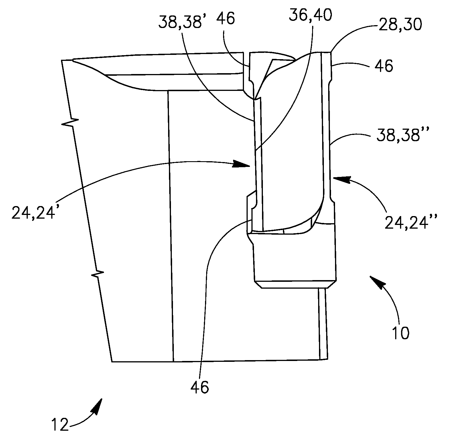
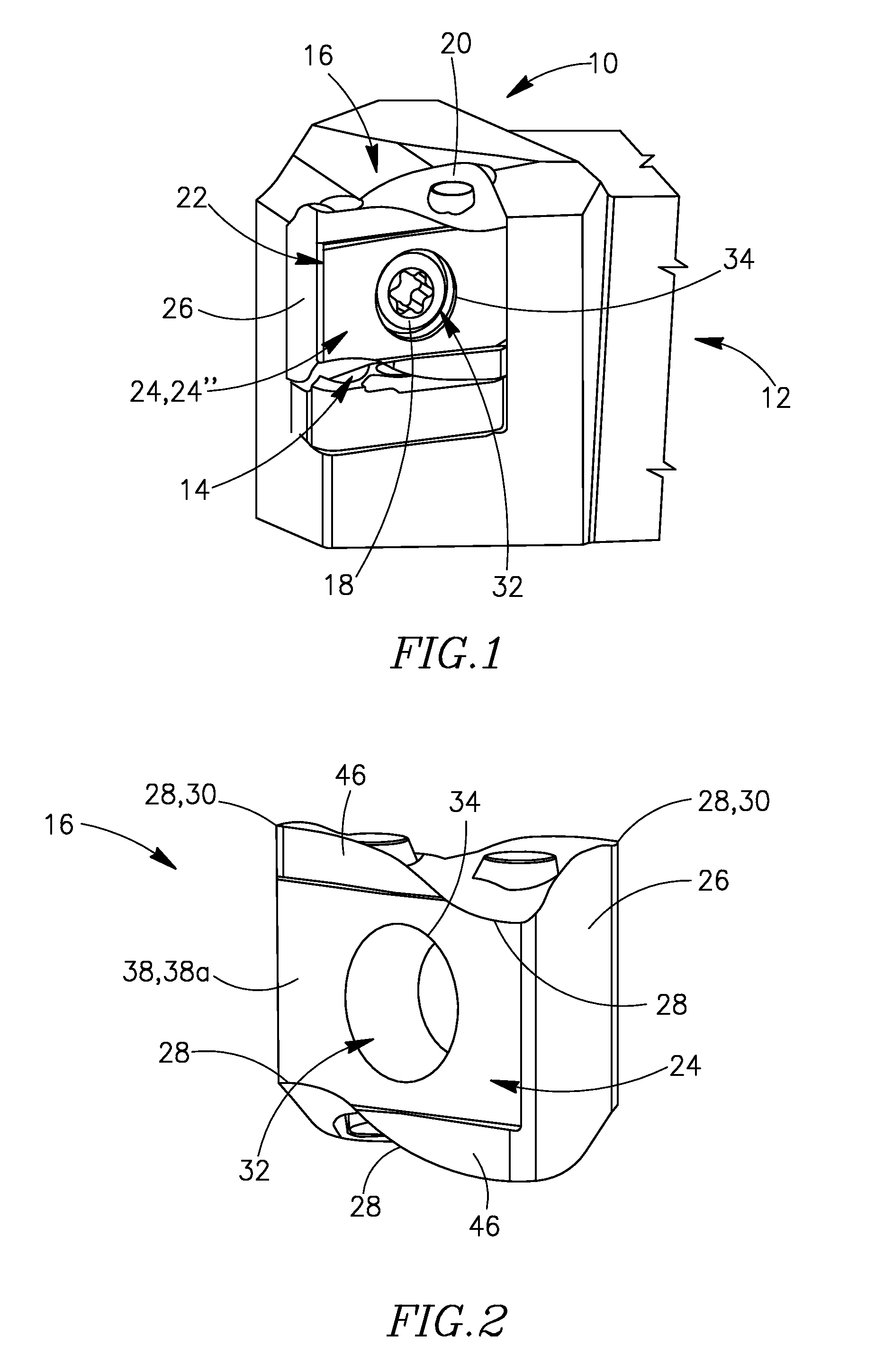
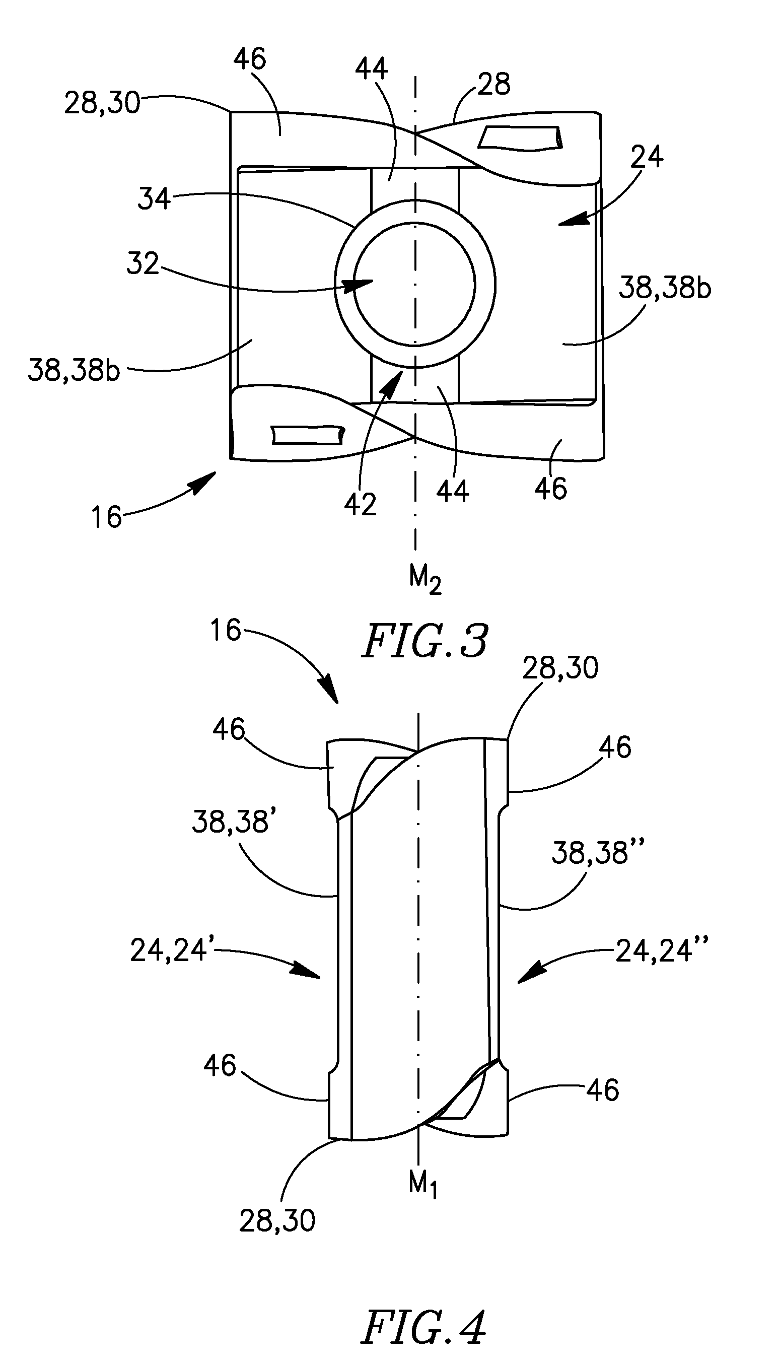
A cutting tool includes a cutting insert releasably retained therein. The cutting insert has at least a first non-planar side surface, which includes a planar portion that is recessed with respect to other portions of the side surface such as the cutting edges thereof. The planar portion may be spaced apart from the cutting edges associated with that side surface. The planar portion is the only portion of the side surface to engage an abutment region or regions of a supporting wall of the cutting tool. The cutting insert may be double-sided, and include a second, opposing side surface having a respective planar portion formed therein, wherein the two opposing side surfaces interchange positions upon indexing of the cutting insert. The planar portion of the second side surface, which does not engage the abutment region or regions of supporting wall, does not interfere with the cutting operation, or the functionality of the cutting insert.

Description

FIELD OF THE INVENTION[0001]The present invention relates to a cutting insert and to a cutting tool therefor, the cutting insert having a recessed planar portion formed on a side surface thereof.BACKGROUND OF THE INVENTION[0002]Many indexable cutting inserts used for turning, milling or other metal cutting operations include one or more operative and / or non-operative surfaces having non-planar shapes, for example, having concave, convex, bent, sunken, undulating, or bowed shapes, or other different non-planar shapes. These surfaces assume their non-planar shapes, for example, in order to satisfy various constraints arising from functional and geometrical requirements involved in the design of the cutting insert.[0003]Some indexable, double-sided cutting inserts, for example, have two opposing surfaces, for example, two opposing side surfaces that assume identical, non-planar shapes. When such a cutting insert is retained in an insert pocket of a cutting tool, a first of the two oppo...

Claims


Application Information

Patent Timeline
IPC IPC(8): B23B27/16B23B27/22
CPCB23B27/145B23B2200/081B23B2200/082B23B2200/125B23B2200/128Y10T407/23B23B2200/369B23B2205/12Y10T407/2274Y10T407/235B23B2200/202B23B27/14B23B27/16B23C5/20
Inventor HECHT
Owner ISCAR LTD
Learn More