
Intake duct liner for a turbofan gas turbine engine

a technology of gas turbine engine and intake duct liner, which is applied in the direction of machines/engines, liquid fuel engines, transportation and packaging, etc., can solve the problems of large energy exchange between different tone frequencies and reduce the effectiveness of the buzz-saw tone liner at the sensitive frequencies

Inactive Publication Date: 2010-11-18
ROLLS ROYCE PLC
View PDF11 Cites 17 Cited by
  • Summary
  • Abstract
  • Description
  • Claims
  • Application Information

AI Technical Summary

Benefits of technology

[0006]Accordingly, the present invention seeks to provide a novel intake duct liner for a turbofan gas turbine engine, which reduces, preferably overcomes, the above-mentioned problem.
[0008]A buzz-saw tone noise liner is a liner arranged to reduce the low frequency buzz-saw noise produced when the tips of the fan blades rotate with supersonic velocities and there are slight differences in the fan blades.

Problems solved by technology

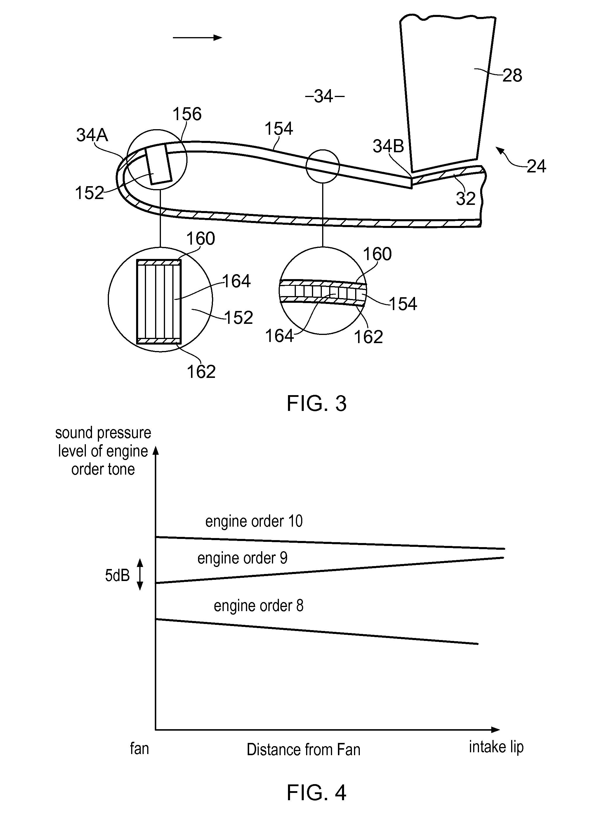
However, the buzz-saw tone noise propagates non-linearly in an upstream direction from the fan within the intake duct and there may be a large exchange of energy between different tone frequencies.
However, because the buzz-saw tone noise propagation is non-linear, noise may leak back into these sensitive frequencies after the noise has passed the deep buzz-saw tone noise liner so that the effectiveness of the buzz-saw tone noise liner at the sensitive frequencies is reduced.
This is particularly true if the engine order tone level is initially low due to liner attenuation.

Method used


Image

  • Intake duct liner for a turbofan gas turbine engine
  • Intake duct liner for a turbofan gas turbine engine
  • Intake duct liner for a turbofan gas turbine engine

Examples


Embodiment Construction

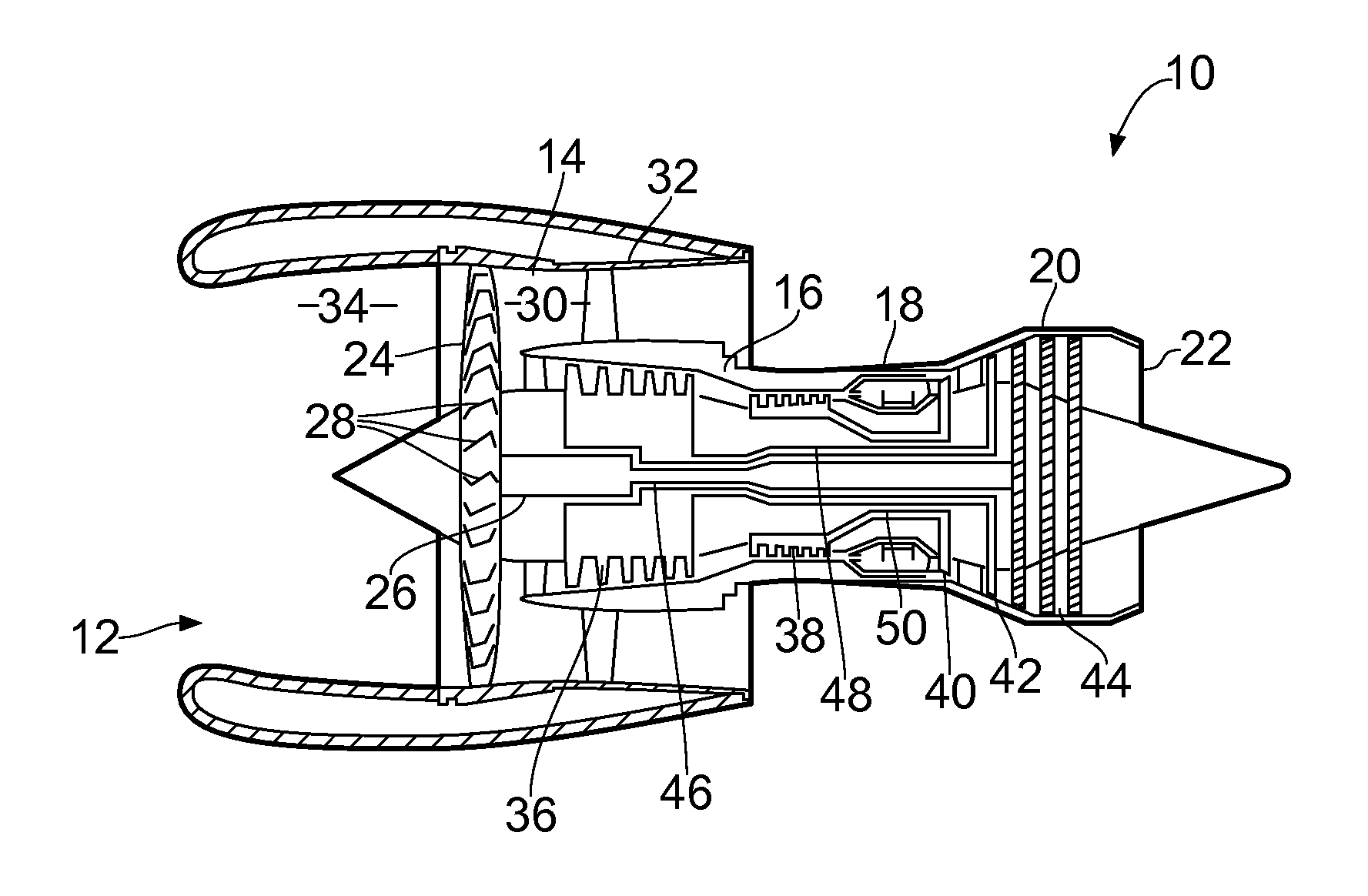
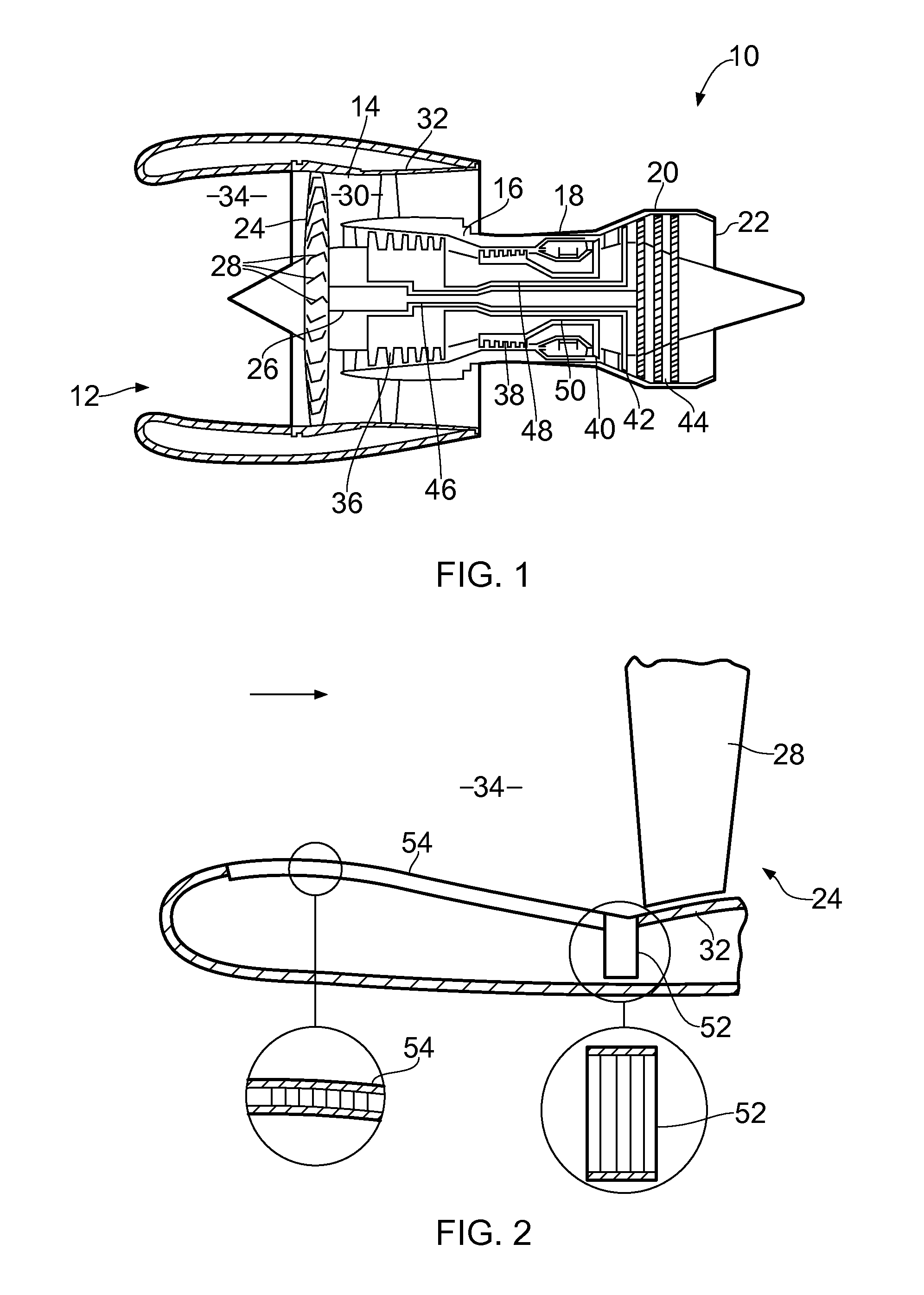
[0028]A turbofan gas turbine engine 10, as shown in FIG. 1, comprises in axial flow series an intake 12, a fan section 14, a compressor section 16, a combustion section 18, a turbine section 20 and an exhaust 22. The fan section 14 comprises a fan 24, which includes a fan rotor 26 carrying a plurality of circumferentially spaced radially outwardly extending fan blades 28. The fan blades 28 extend across a fan duct 30 defined at its radially outer by a fan casing 32. An intake duct 34 is positioned axially upstream of the fan 24 and is also defined at its radially outer extremity by the fan casing 32. The compressor section 16 comprises an intermediate pressure compressor 36 and a high-pressure compressor 38. The turbine section 20 comprises a high-pressure turbine 40, an intermediate pressure turbine 42 and a low-pressure turbine 44. The low pressure turbine 44 is arranged to drive the fan 24 via a first shaft 46, the intermediate pressure turbine 42 is arranged to drive the interme...


PUM


Abstract

A turbofan gas turbine engine comprises a fan and an intake duct upstream of the fan. The fan comprises a fan rotor having a plurality of fan blades. The intake duct has a liner, the liner comprising an acoustic liner positioned upstream of the fan and a buzz-saw tone noise liner positioned upstream of the acoustic liner. The buzz-saw tone noise liner is positioned substantially at, or near, an upstream end of the intake duct. The intake duct has a lip and the buzz-saw tone noise liner is positioned at, or near, the lip.

Description

CROSS REFERENCE TO RELATED APPLICATION[0001]This application is entitled to the benefit of British Patent Application No. GB 0908128.2, filed on May 12, 2009.FIELD OF THE INVENTION[0002]The present invention relates to an intake duct liner for a turbofan gas turbine engine.BACKGROUND OF THE INVENTION[0003]It is known from our U.S. Pat. No. 4,122,672 to provide a deep buzz-saw tone noise liner directly upstream of a fan in an intake duct of a turbofan gas turbine engine to reduce low frequency buzz-saw noise levels and to provide a shallower acoustic liner upstream of the buzz-saw tone noise liner in the intake duct of the turbofan gas turbine engine.[0004]Buzz-saw noise, also called multiple tone noise or combination tone noise, occurs when the tips of the fan blades of a fan of a turbofan gas turbine engine rotate with supersonic velocities. The spectrum of buzz-saw noise contains energy in a wide range of harmonics of the engine rotation frequency; as opposed to blade passing freq...

Claims


Application Information

Patent Timeline
Patent Type & Authority Applications(United States)
IPC IPC(8): F04D29/66B64D33/02
CPCB64D33/02B64D2033/0286B64D2033/0206
Inventor SCHWALLER, PETER JEAN GABRIEL
Owner ROLLS ROYCE PLC
Learn More