Crop residue chopping and distributing arrangement for a combine harvester

Active Publication Date: 2010-11-18
DEERE & CO
View PDF10 Cites 15 Cited by
  • Summary
  • Abstract
  • Description
  • Claims
  • Application Information

AI Technical Summary

Benefits of technology

[0015]When acting upon the discharge blowers axially, the system may deflect the crop residue stream to the discharge blowers at a greater angle in reference to the rotational axis in a central region than in outer regions. In other words, the system may be arranged such that the crop residue stream in the central region impacts on the paddles of the discharge blower at a relatively flat angle in reference to the radius of the discharge blower. Consequently, the speed of the crop residues generated by the straw chopper is be

Problems solved by technology

In contrast to this, the discharge blowers of EP 1 269 822 A1, EP 1 277 387 A1, EP 1 514 466 A2 and EP 1 532 858 A1 have a slightly smaller diameter, yet this has the aforementioned disadvantage that the outer regions of the discharge blowers need to deflect the crop residues impacting at this location by approximately 180° an

Method used


Image

  • Crop residue chopping and distributing arrangement for a combine harvester
  • Crop residue chopping and distributing arrangement for a combine harvester
  • Crop residue chopping and distributing arrangement for a combine harvester

Examples


Embodiment Construction

[0027]In this document, “front”, “forward”, “in front of”, and similar terms refer to the direction of movement of the vehicle when it travels through the field in a straight line harvesting crop. “Rear”, “rearward”, “behind”, and similar terms refer to the opposite direction. “Lateral”, “laterally”, and similar terms refer to a direction that is perpendicular to the above direction of movement and is generally horizontal.

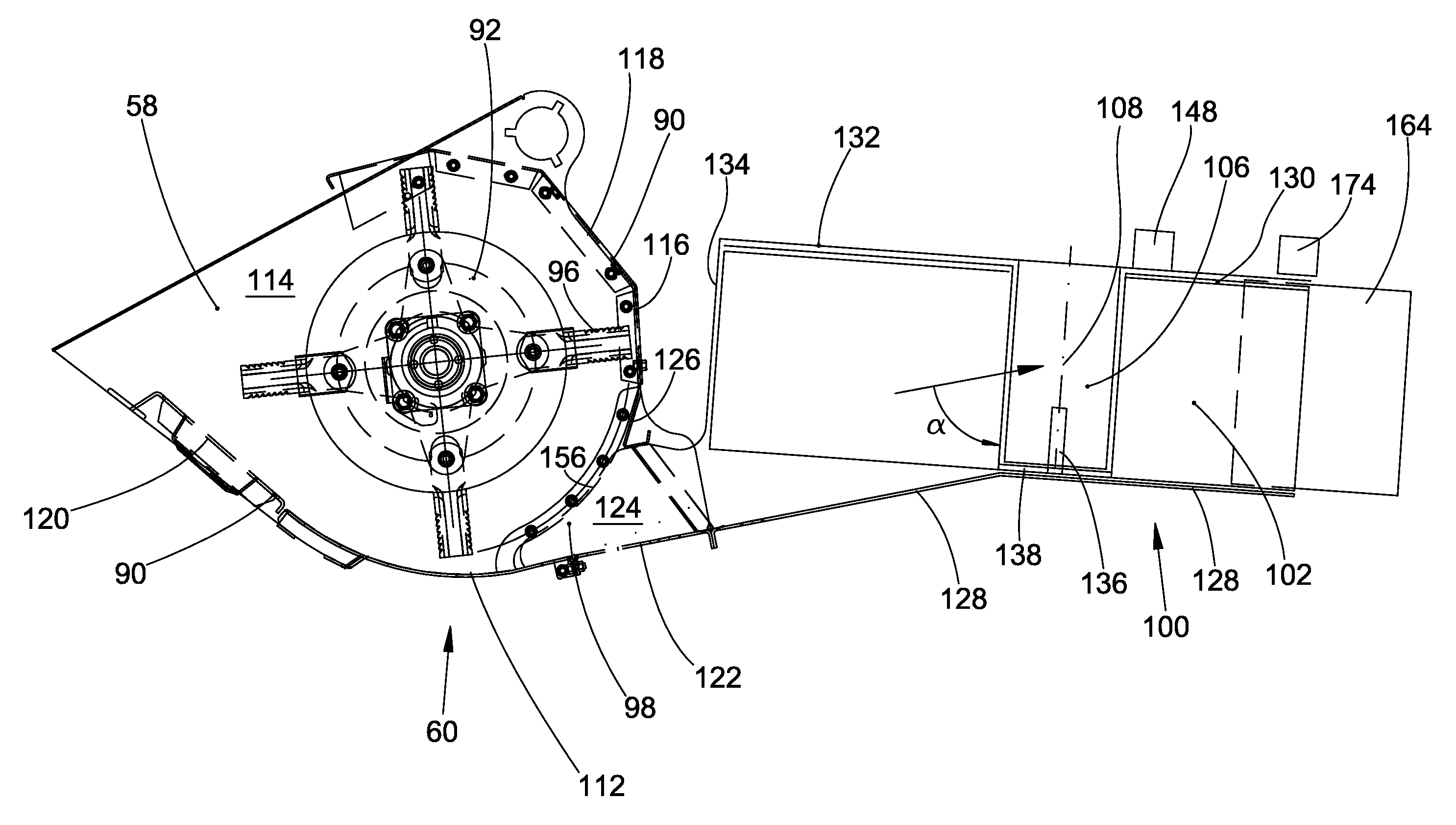
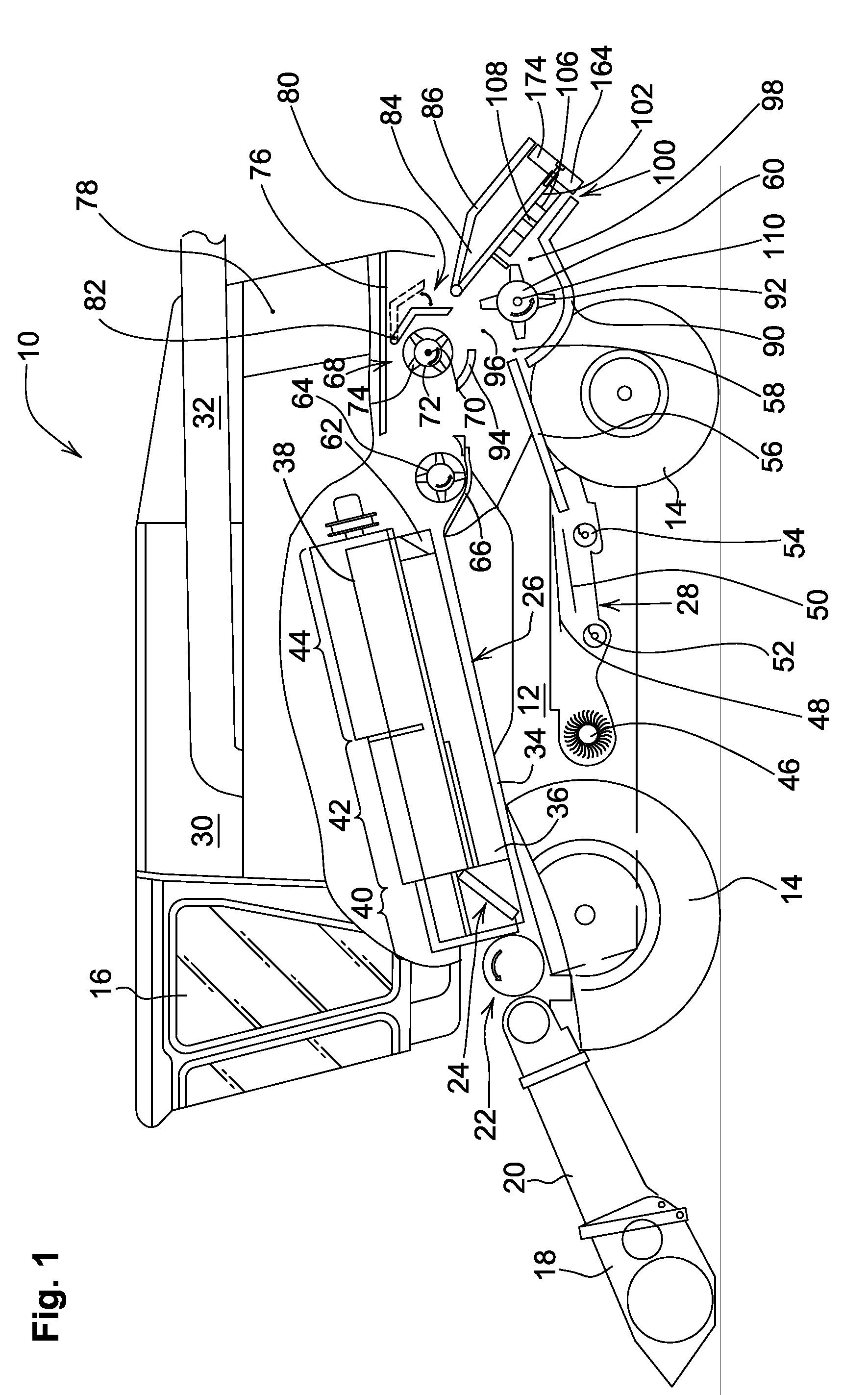
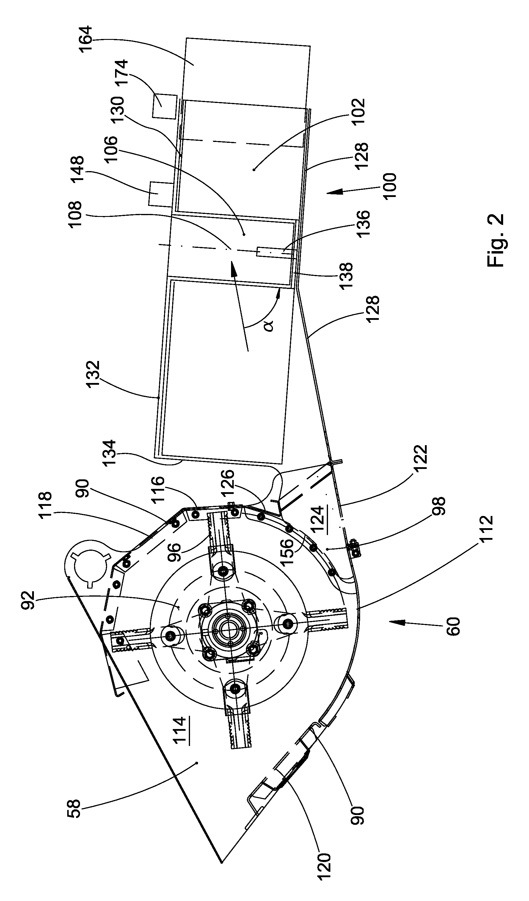
[0028]FIG. 1 shows an agricultural combine harvester 10 with an undercarriage 12 with wheels 14 that are in contact with the ground, wherein said wheels are fixed on the undercarriage 12 and serve for propelling the combine harvester 10 in a forward direction that extends toward the left in FIG. 1. The operation of the combine harvester 10 is controlled from the operator's cabin 16. A cutting unit 18 is used for harvesting the grain-bearing crop and feeding the harvested crop to a slope conveyor 20. The harvested crop is fed to a guide drum 22 by the slope conveyor...


PUM


Abstract

The invention pertains to a crop residue chopping and distributing arrangement for a combine harvester (10) with a straw chopper (60) and two discharge blowers (100), wherein a guide element (150) that distributes the crop residue stream over the two discharge blowers (100) is arranged between said blowers. Passages (162) remain between the guide element (150) and the discharge blowers (100) such that the crop residues can be rearwardly discharged onto the field by the straw chopper (60) through said passages. Outer guide elements (141) are provided between the straw chopper (60) and the discharge blowers (100) in order to deflect the outer regions of the crop residue stream inward. The straw chopper housing (19) may feature a curved bottom (112) that axially conveys the crop residues to the discharge blowers (100) at an angle, wherein a flat crop residue guide element (112) is arranged between the straw chopper housing (90) and the discharge blowers (100).

Description

FIELD OF THE INVENTION[0001]The invention pertains to a crop residue chopping and distributing arrangement for a combine harvester.BACKGROUND OF THE INVENTION[0002]Agricultural combine harvesters are large machines that harvest, thresh, separate and clean agriculturally cultivated grain-bearing crops. The obtained clean grain is stored in a grain tank arranged on the combine harvester. The threshed straw is usually either chopped and distributed on the field over the width of the cutting unit or conveyed around the straw chopper and deposited on the field in non-chopped form in a windrow in order to be subsequently picked up by a baler. The crop residues ejected out of the rear outlet of the cleaning device such as chaff and small straw particles are distributed on the field by a chaff spreader or conveyed through the straw chopper and distributed on the field.[0003]DE 199 08 111 C1 describes a combine harvester with a straw chopper and two discharge blowers that are arranged latera...

Claims


Application Information

Patent Timeline
IPC IPC(8): A01F12/40
CPCA01D41/1243
Inventor POHIMANN, NORBERTLAUER, FRIEDRICH K.WEICHHOLDT, DIRKPRIESNITZ, RICOKLEIN, OLIVER
Owner DEERE & CO
Why Eureka
Try Eureka