Surgical saw blade device and system

a technology blades, which is applied in the field of surgical saw blades, can solve the problems of long-standing problems of surgeons, the loss of efficiency in such translation mechanisms, and the creation of many friction between the moving internal parts, so as to improve the tracking of the elongate monolithic blades, improve the accuracy of cutting, and improve the effect of chip removal efficiency

Active Publication Date: 2010-11-18
SYNVASIVE TECH
View PDF53 Cites 59 Cited by
  • Summary
  • Abstract
  • Description
  • Claims
  • Application Information

AI Technical Summary

Benefits of technology

[0034]In another aspect, embodiments of the invention provide a method for surgical cutting of bone. The bone is contacted with a distal cutting edge of an elongate monolithic blade. The distal end comprises a plurality of teeth. Each tooth ends in a distal tip. The distal tips of the teeth are positioned on a line perpendicular to the central longitudinal axis of the elongate monolithic blade such that said teeth provide better tracking of the elongate monolithic blade when forming a kerf in the bone. The bone is cut by oscillatin

Problems solved by technology

Surgeons have long faced the problem of reaching narrow and deep recesses with power-driven surgical saw blades.
By providing for such required freedom of motion, efficiency can be lost in such translation mechanisms.
Thus, much friction between the moving internal parts can be created when the surgical saw blade is in use.
As such, efficiency can further be lost between the power source and the cutting edge of the surgical saw blade with a translation mechanism.
As a result, the teeth of the cutting edges engage bone at a very sharp and unstable angle.
This sharp, unstable engagement angle can cause the surgical saw blade to buck and “kick”, i.e., become caught upon the bone being cut by the point of a tooth.
This tendency of the surgical saw blade to buck and “kick” will typically reduce the overall cutting efficiency and accuracy of the saw blade assembly.
The instability of the surgical saw blade can also translate back to the surgeon's hand, increasing the risk of an inaccurate bone cut.
However, maintaining a tighter grip increases the fatigue of the surgeon and the instability can manifest itself as torsional stresses placed upon the moving parts of the saw blade assembly.
With the saw blade as

Method used


Image

  • Surgical saw blade device and system
  • Surgical saw blade device and system
  • Surgical saw blade device and system

Examples


Embodiment Construction

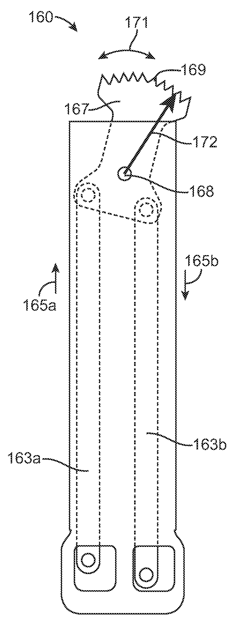
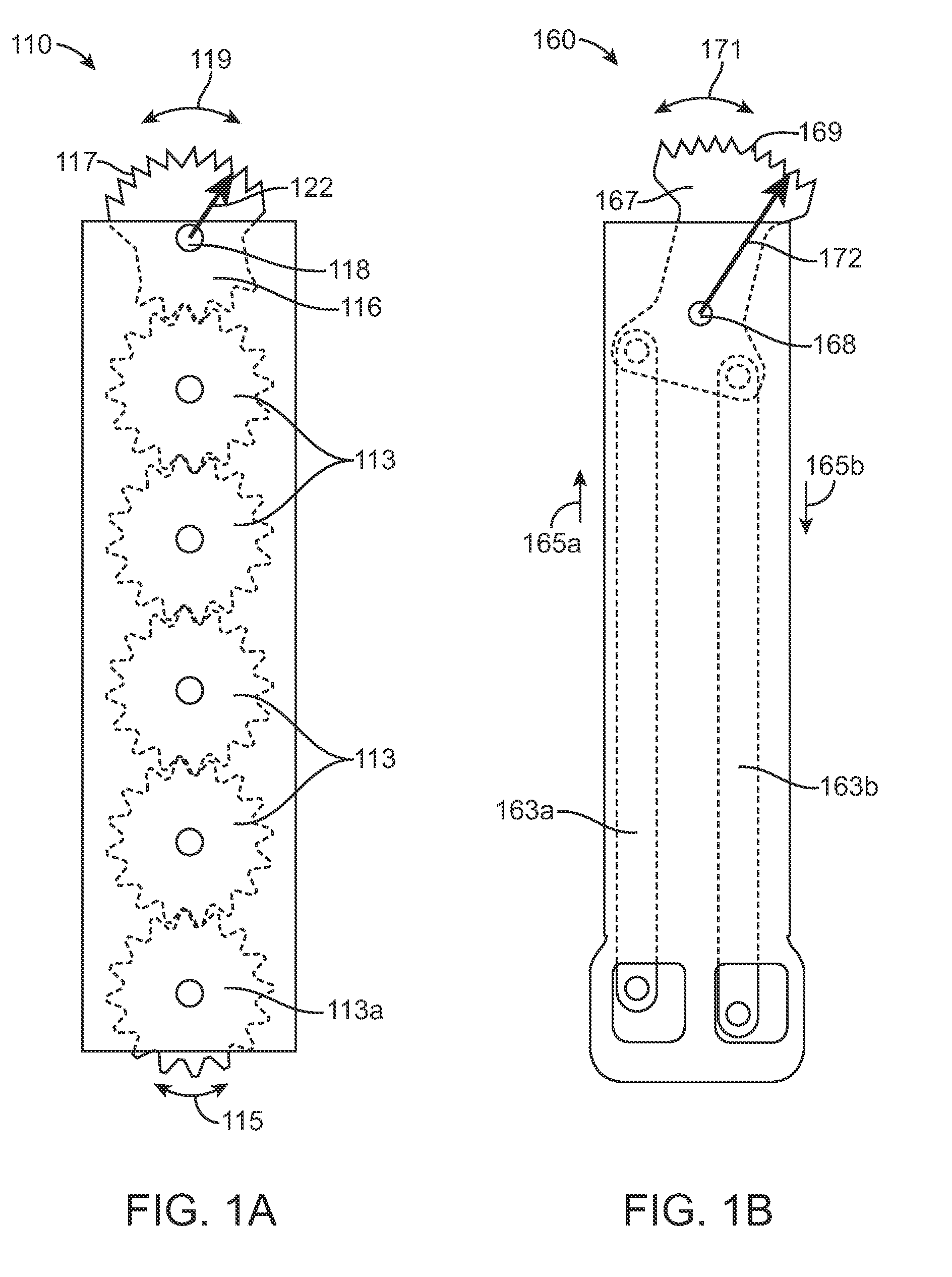
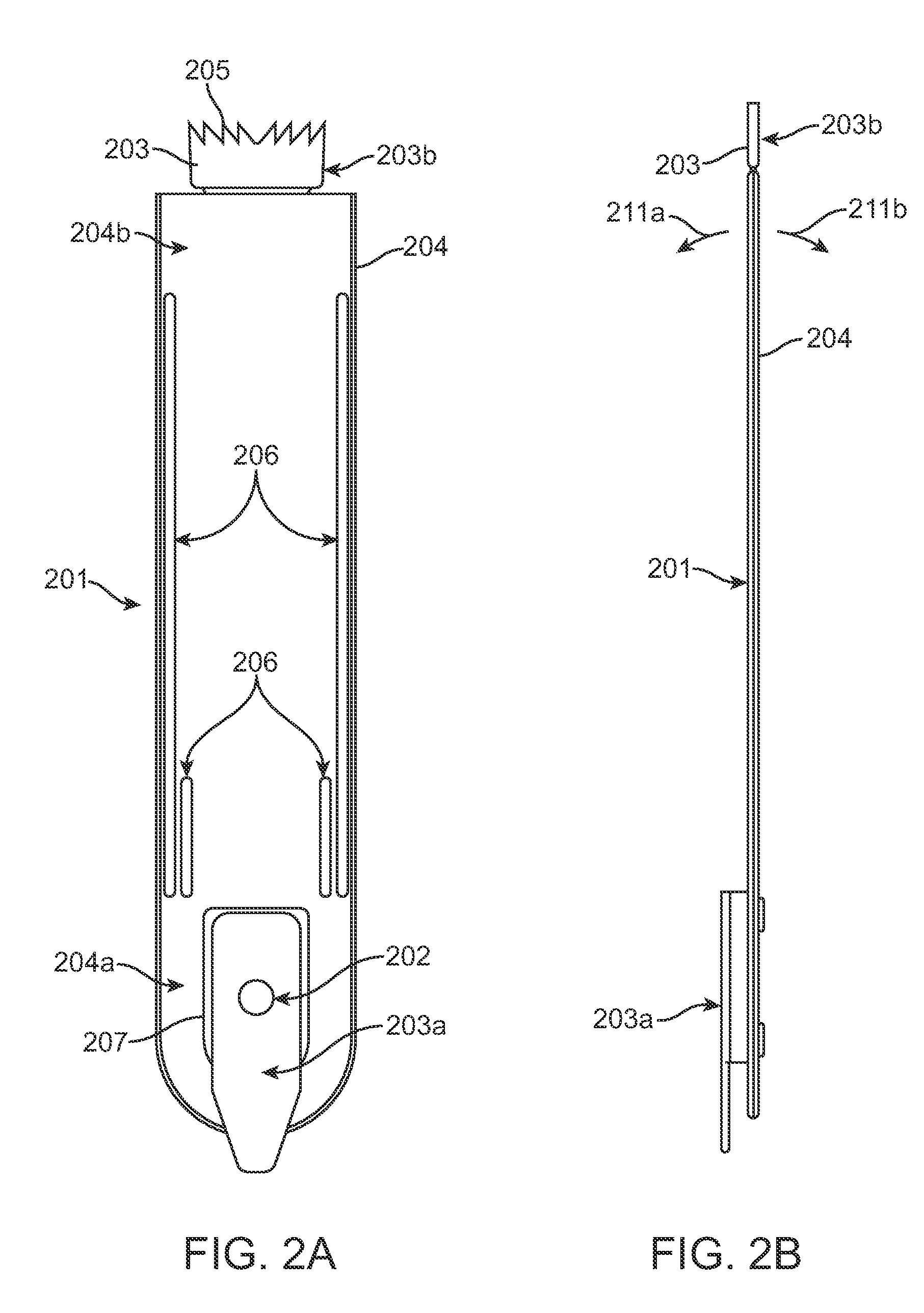
[0061]FIGS. 2A and 2B respectively show front and side views of a saw blade assembly 201 according to embodiments of the invention. The saw blade assembly 201 comprises an elongate monolithic blade 203 and an elongate sheath 204. The elongate monolithic blade 203 has a unitary construction with no moveably connected parts, making it much more mechanically efficient than known surgical saw blades employing translation mechanisms with moveably connected moving internal parts. Typically, the majority of the elongate monolithic blade 203 is housed within the interior of the elongate sheath 204. The elongate sheath 204 will typically have no other moving internal parts besides the elongate monolithic blade 203. The elongate monolithic blade 203 has a proximal end 203a and a distal cutting end 203b comprising a cutting edge 205 which typically comprises a plurality of sharp projections or teeth. The elongate sheath 204 has a proximal end 204a and a distal end 204b, which as shown in FIGS....


PUM


Abstract

A saw blade assembly for use with a driver having an oscillatory drive member comprises an elongate sheath and an elongate monolithic blade. The sheath's proximal end is removably mountable on the driver. The sheath has an open interior which receives the blade. The blade's proximal end is pivotably mounted to the sheath's proximal end. The blade's distal cutting end extends out of the sheath's distal end and is transverse to the blade's central longitudinal axis. When cutting bone, the drive member pivots the blade's cutting end back and forth in an arc about a pivot point at the blade's proximal end while the driver holds the sheath stationary to protect surrounding tissues from the motions of the remainder of the blade. The long pivot radius between the proximal pivot point and the distal cutting end contributes to minimizing the angle of engagement of the cutting end to the bone.

Description

BACKGROUND OF THE INVENTION[0001]1. Field of the Invention[0002]The following invention relates generally to instruments for cutting bone during surgery. More particularly, the instant invention is directed toward surgical saw blades adapted to be operatively coupled to powered surgical instruments.[0003]2. Description of the Prior Art[0004]Powered oscillating surgical saws with coupled bone cutting surgical saw blades are widely used in orthopedic surgery. Surgeons have long faced the problem of reaching narrow and deep recesses with power-driven surgical saw blades. During surgery, the protection of soft tissue such as tendons, ligaments, muscles, vascular and neurological structures is crucial. As such, various power transmission mechanisms, which transmit power from the proximally (near the surgeon or user) disposed powered oscillating surgical saw to the distal (far end) cutting edge of the surgical saw blade, have been designed to limit the midline oscillatory excursion of the...

Claims


Application Information

Patent Timeline
IPC IPC(8): A61B17/00
CPCA61B17/14A61B17/148A61B17/141A61B17/142
Inventor FISHER, MICHAELCHANA, BARJINDER
Owner SYNVASIVE TECH
Why Eureka
Try Eureka