Surgical instrument

a surgical instrument and instrument body technology, applied in the field of surgical instruments, can solve the problems of bulky and bulky prior art tools, difficult and time-consuming operation of tools,

Active Publication Date: 2010-11-18
BIOMET UK
View PDF102 Cites 169 Cited by
  • Summary
  • Abstract
  • Description
  • Claims
  • Application Information

AI Technical Summary

Benefits of technology

[0013]The provision of a plurality of guide holes or bores enables the surgeon to select an appropriate bore which might compensate for minor misalignment of the instrument. Furthermore, having groups of bores aligned

Problems solved by technology

Such tools are often difficult and time consuming to operate, and are inaccurate.
Many of the tools of the prio

Method used


Image

  • Surgical instrument
  • Surgical instrument
  • Surgical instrument

Examples


Embodiment Construction

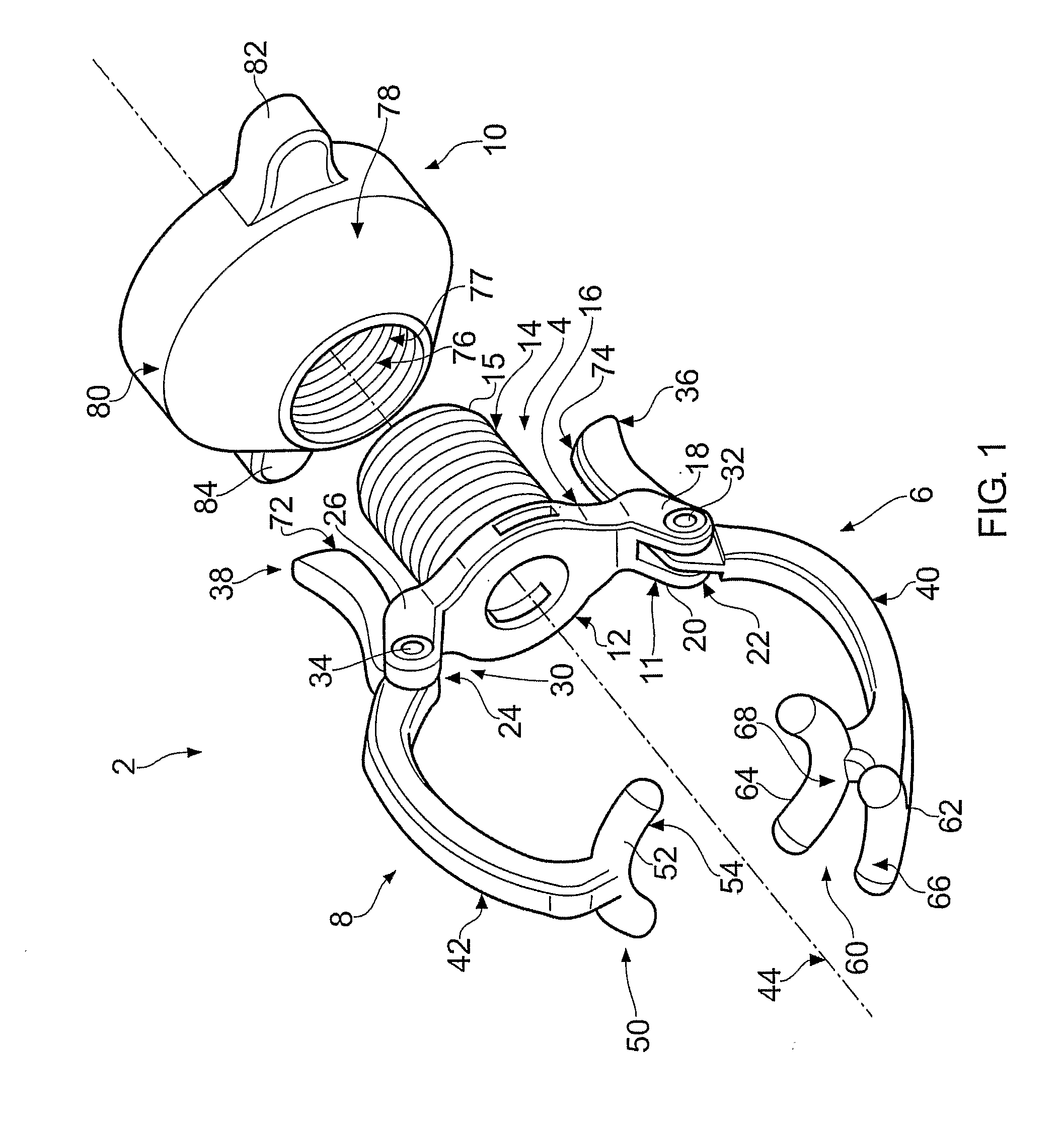
[0025]With reference to FIG. 1, a surgical instrument 2 comprises a body portion 4, a pair of opposed first and second arms 6, 8 pivotally connected to the body portion 4, and a nut 10 mountable on the body portion 4. The body portion 4 comprises an annular flange 12 and a post 14 that carries an external thread 15.

[0026]In this specification, the terms “distal” and “distally” mean towards the threaded end of the surgical instrument 2, and the terms “proximal” and “proximally” mean towards the opposite end of the surgical instrument 2.

[0027]The post 14 projects substantially perpendicularly from a distal surface 16 of the flange 12. A first tab 11 projects from a first (or inferior) side of the flange 12 and is bifurcated. A recess 22 is defined between substantially parallel forks 18, 20 of the first bifurcated tab 11. A second bifurcated tab 30 projects from an opposite (or superior) side of the flange 12. A second recess 24 is defined between substantially parallel forks 26, 28 o...


PUM


Abstract

An instrument (2) for aligning a surgical tool, the instrument (2) comprising, a body portion (4) having a tool guide (90), first and second arms (6), (8) operatively connected to the body portion (4) and adapted to engage a bone, and urging means (10), acting between the body portion (4) and the first and second arms (6), (8), for urging the first and second arms (6), (8) into engagement with a predetermined portion of a bone, thereby clamping the arms (6), (8) onto the bone and aligning the tool guide (90) with the bone.

Description

[0001]This invention relates to a surgical instrument and particularly, but not exclusively, relates to an instrument having a tool guide and a clamping arrangement, the clamping arrangement clamping the instrument to a bone, and at the same time aligning the tool guide with the bone.BACKGROUND[0002]During all types of joint replacement surgery, and in many other surgical procedures, it is necessary to make specific cuts or to drill holes into specific areas of bone. Both the point and angle of entry of the cut or drill hole is important. This is particularly so in the case, for example, of femoral head resurfacing, where it is necessary to drill a pilot hole that passes through the centre of the femoral neck at a specific angle with respect both to the epicondylar axis and the femoral shaft axis. Guide tools exist to aid surgeons in the placement of bone cuts and guide holes. Such tools are often difficult and time consuming to operate, and are inaccurate. Many of the tools of the ...

Claims


Application Information

Patent Timeline
IPC IPC(8): A61B17/56
CPCA61B17/175
Inventor SINGHAL, KESHAVPITKANEN, HEIKKI VIHELMMETCALFE, NICK JAMES THEOPHILIUS
Owner BIOMET UK
Why Eureka
Try Eureka