Computer System Having RFID Reading/Writing Function

Inactive Publication Date: 2010-11-25
YEONG CHYI ELECTRONICS
View PDF10 Cites 0 Cited by
  • Summary
  • Abstract
  • Description
  • Claims
  • Application Information

AI Technical Summary

Benefits of technology

[0011]As such, the present invention provides a solution to the difficulties of the con

Problems solved by technology

However, if an object can be developed to have the capability of actively informing its related information, it may save a lot of manpower and reduce errors occurred during manually reading operation.
However, the conventional RFID system is usually very expansive.
Des

Method used


Image

  • Computer System Having RFID Reading/Writing Function
  • Computer System Having RFID Reading/Writing Function
  • Computer System Having RFID Reading/Writing Function

Examples


Embodiment Construction

[0015]The accompanying drawings are included to provide a further understanding of the invention, and are incorporated in and constitute a part of this specification. The drawings illustrate embodiments of the invention and, together with the description, serve to explain the principles of the invention.

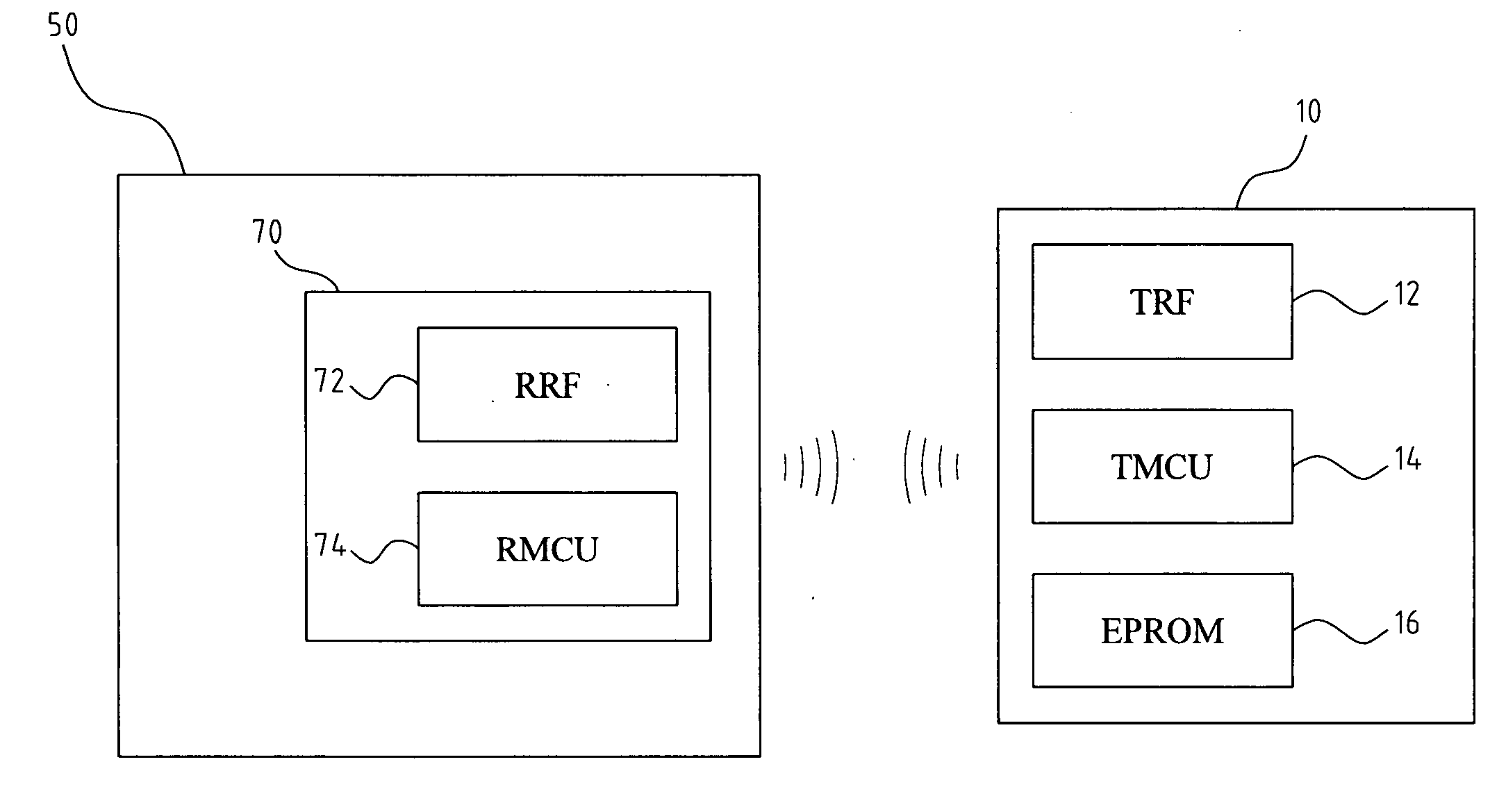
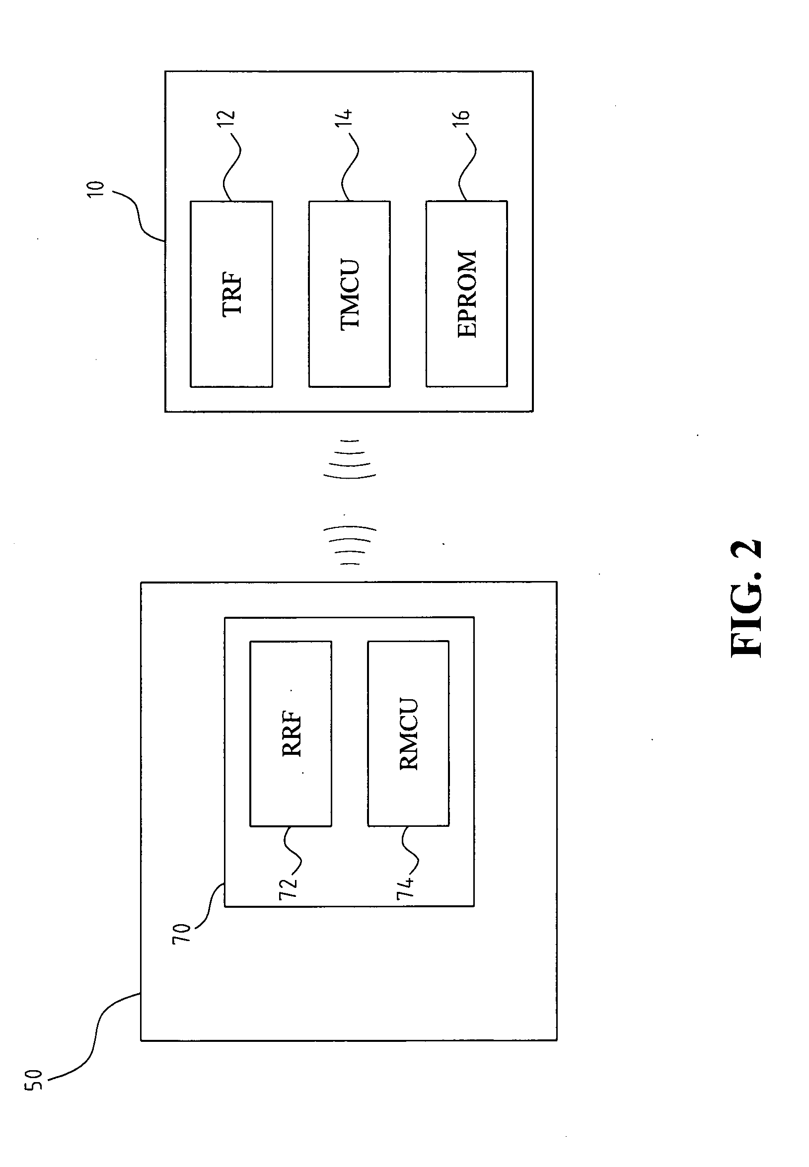
[0016]FIG. 2 is schematic diagram illustrating an architecture of a computer system having an RFID reading / writing function according to an embodiment of the present invention. Referring to FIG. 2, the present invention provides a computer system including a computer device 50 and a modulized RFID reader 70 assembled inside the computer device 50. The modulized RFID reader 70 is a chip or a module interface card including the circuit as well as the functions of the conventional RFID reader as discussed above integrated therein. In such a way, the chip or module interface card can be assembled to a certain assembly of the computer device 50. The assembly for example can be a main boar...


PUM


Abstract

A computer system having an RFID reading/writing function is provided. The computer system includes a computer device, and a modulized RFID reader. The modulized RFID reader is an RFID reader module integrated with functions and the circuit of the conventional RFID reader. The RFID reader module can be integrated inside the computer device. Therefore, the computer system of the present invention is multifunctional and has at least an RFID reading/writing function. As such, the modulized RFID reader is adapted for mass production, and is convenient for testing and assembling. Therefore, the modulized RFID reader can be provided to the customers with a much cheaper price.

Description

BACKGROUND OF THE INVENTION[0001]1. Field of the Invention[0002]The present invention relates generally to a computer system having a radio frequency identification (RFID) reading / writing function, and more particularly, to a computer system having a built-in modulized RFID reader.[0003]2. The Prior Arts[0004]Currently, in most circumstances, the material world and the information world are relatively independent one from another. Even though computer equipments have been widely used for obtaining information, the computer equipment must be handled by human being. However, if an object can be developed to have the capability of actively informing its related information, it may save a lot of manpower and reduce errors occurred during manually reading operation.[0005]FIG. 1 is a schematic diagram illustrating an architecture of a conventional RFID system. Referring to FIG. 1, the RFID system includes an electronic tag, an RFID reader 30, and a computer host 50. The RFID reader 30 and...

Claims


Application Information

Patent Timeline
IPC IPC(8): H04Q5/22
CPCH04Q2213/13095G06K7/0008
Inventor HSIEH, SEN-FANGTAI, KUO-HSIN
Owner YEONG CHYI ELECTRONICS
Why Eureka
Try Eureka