Multidirectional turning endoscope

a multi-directional turning, endoscope technology, applied in the field of medical devices, can solve the problems of inability to bend the front end, need of additional locking devices, and the flexible medical endoscope is unidirectional or bidirectional turning or bidirectional turning, etc., to achieve convenient processing and assembly, reliable positioning, and simple structure

Active Publication Date: 2020-01-28
YOUCARE TECH CO LTD
View PDF3 Cites 0 Cited by
  • Summary
  • Abstract
  • Description
  • Claims
  • Application Information

AI Technical Summary

Benefits of technology

[0006]An object of the present invention is to overcome the drawbacks of the background art described above and to provide a multidirectional turning endoscope which is simple in operation and has the characteristic of stepless self-locking, that is, self-locking at any bending position, thereby achieving high surgical safety.
[0032]The invention has the advantages of reliable positioning, simple structure and convenient processing and assembling. Especially, the present invention adopts the special self-locking bending driving portion, through adjusting the engagement depth between the left or right conical cylinder and the inner wall of the endoscope handle, the compression degree and the restoring force of the spring are adjusted, so as to respectively closely fit the left outer conical face on the left half shaft with the inner conical face of the left conical cylinder, and closely fit the right outer conical face on the right half shaft with the inner conical face of the right conical cylinder, so that the friction force therebetween is balanced with the restoring force of the spring, thereby achieving self-locking. Through the structure described above, the flexible sheath is capable of being locked stepless at any position while bending left and right, so as to meet the requirements of endoscopic free positioning during surgery, reduce the labor intensity of the surgical process, and prevent patient injury caused by misoperation.
[0034]The endoscope according to the present invention is able to control the left-right direction driving rod and the front-rear direction driving rod, so as to realize the front-rear and left-right multidirectional bending of the insertion part of the endoscope, and stepless self-lock in any direction.

Problems solved by technology

The early medical endoscope is rigid, although it is easy to be operated, its front end is unable to be bent for reaching the site with the curved tract.
Most of the existing flexible medical endoscopes are unidirectional turning or bidirectional turning, and are in need of additional locking devices.
Even for a skilled operator, after finding the target with one hand, a long period of control state after bending shall be maintained, consequently, the operator becomes fatigued easily, and the risk of surgery is increased.
Alternatively, the operator locks the bending state with his or her other hand, and releases the lock if the bending state needs to be changed, which increases the complexity of the operation.
In the process of locking and unlocking, the endoscope is likely to cause jitter and lose the target, which is not conducive to the operation.

Method used


Image

  • Multidirectional turning endoscope
  • Multidirectional turning endoscope
  • Multidirectional turning endoscope

Examples


embodiment 1

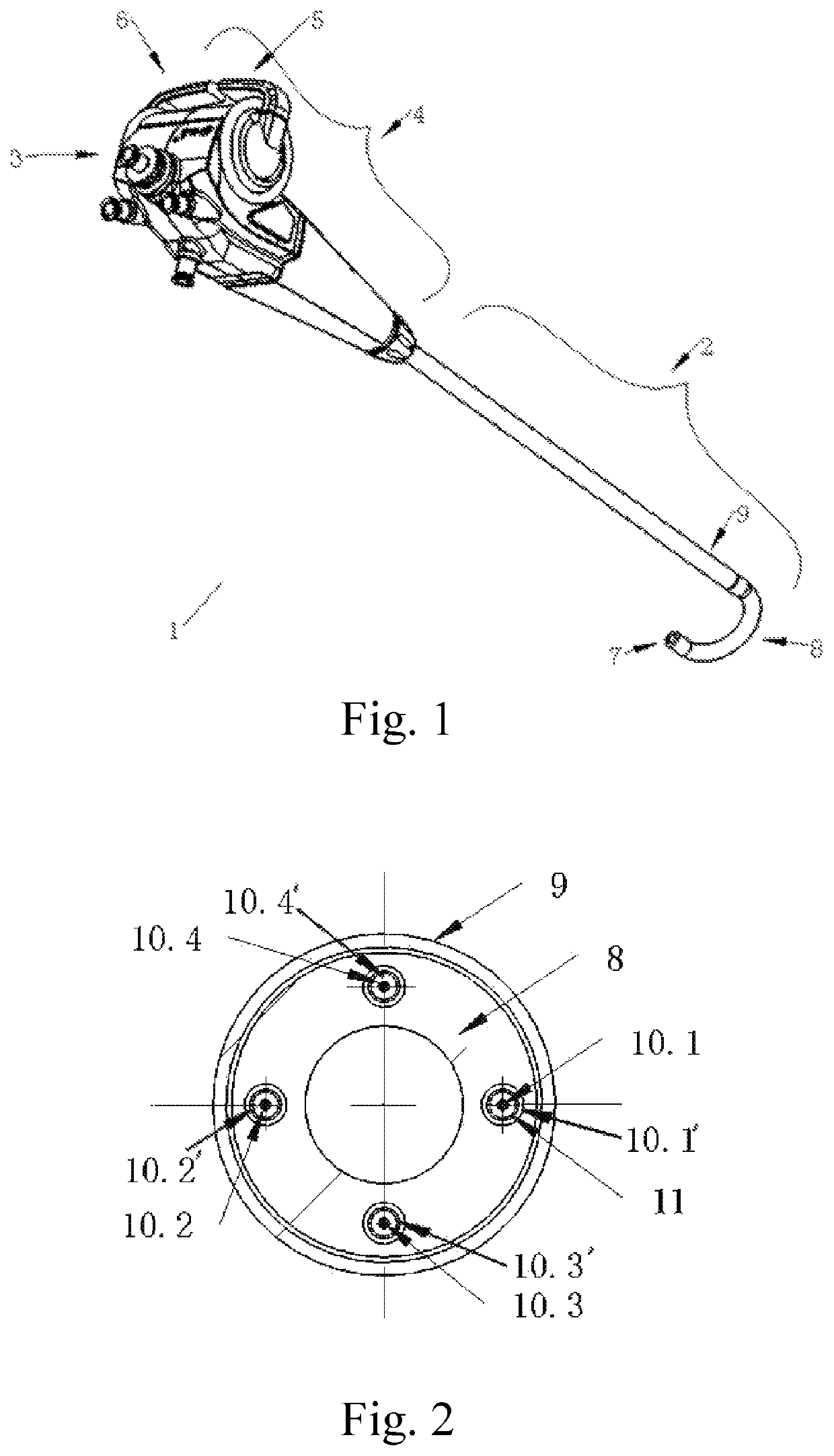
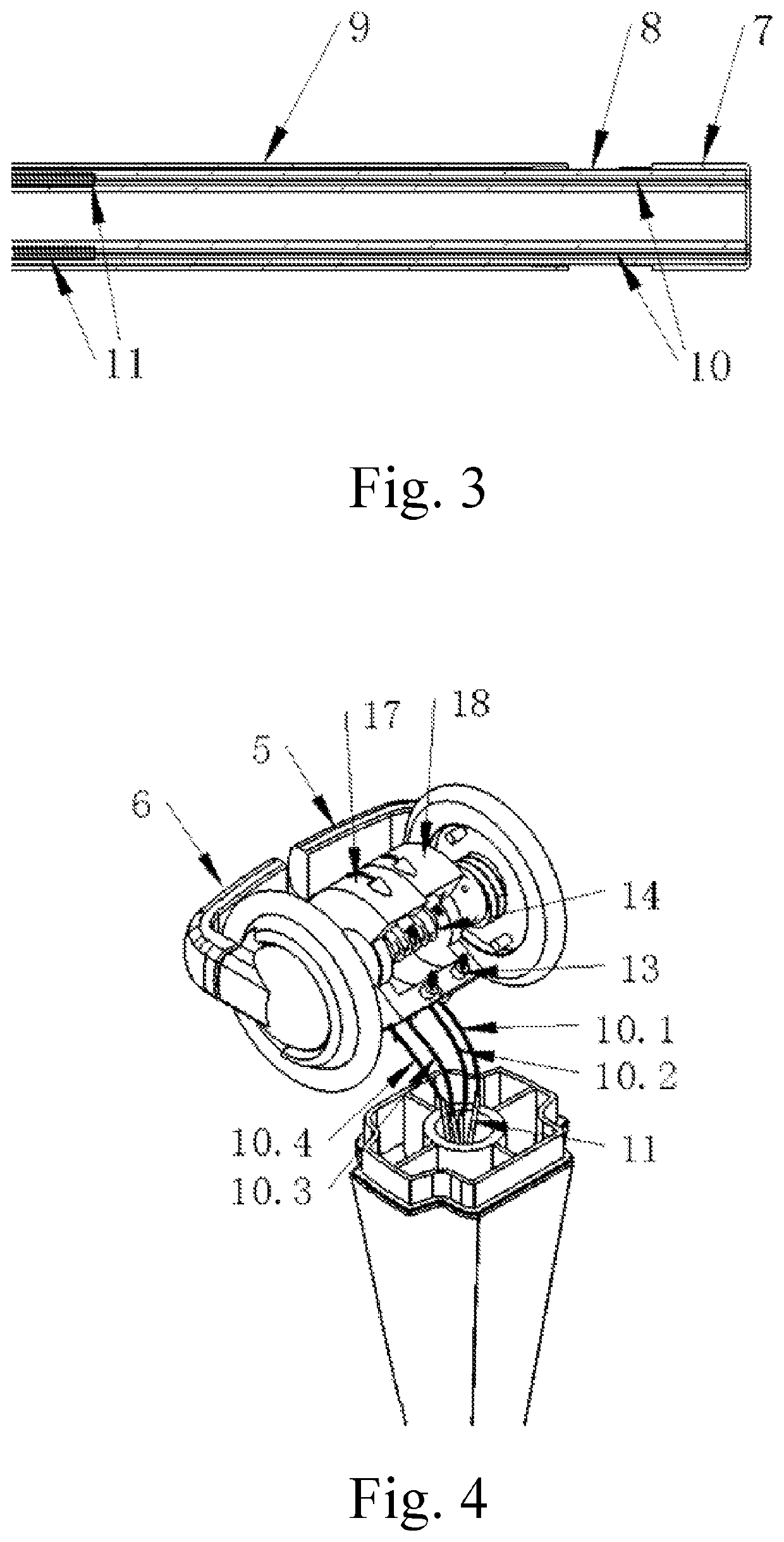
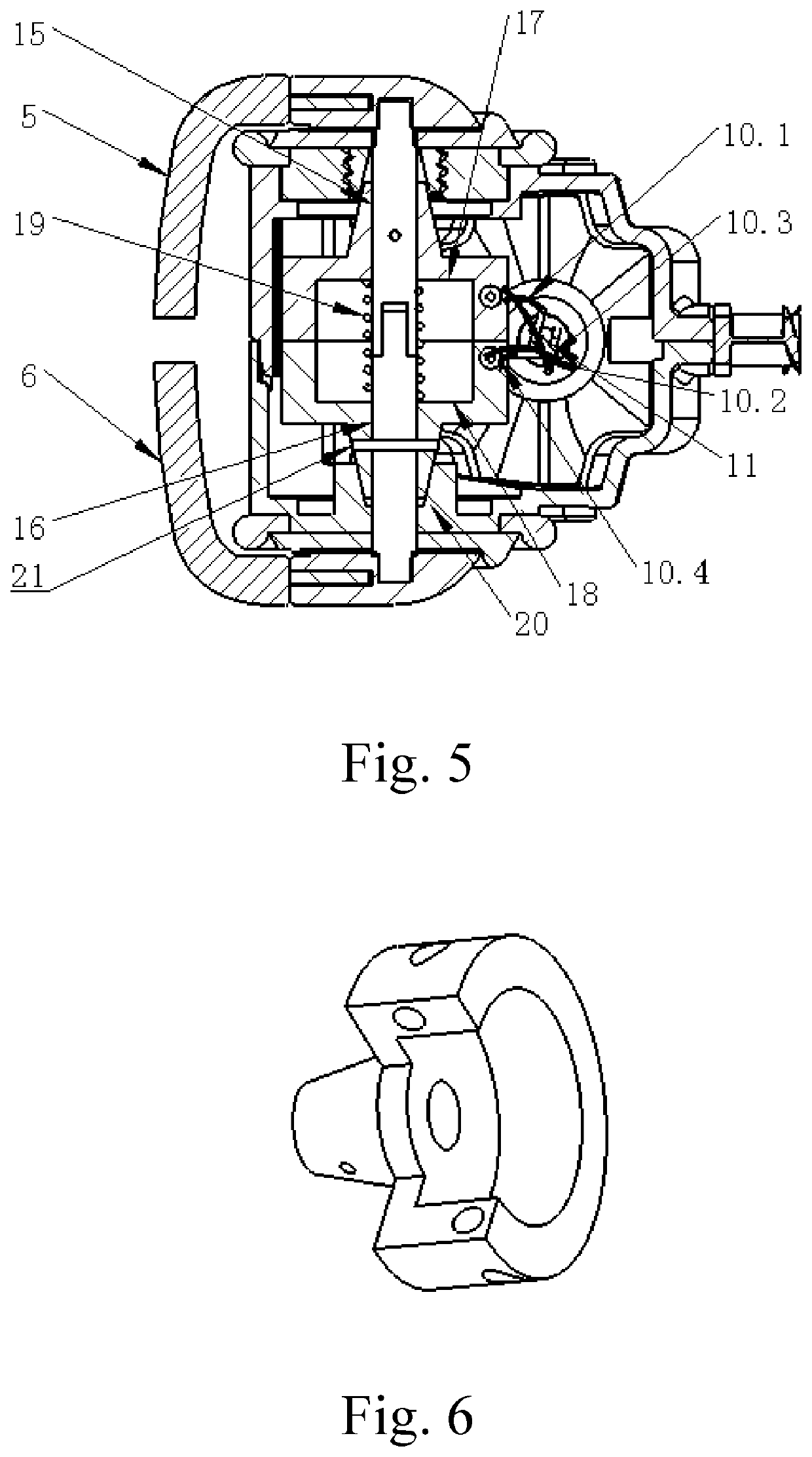
[0043]Referring to FIGS. 1-6, a multidirectional turning endoscope 1 according to a first preferred embodiment of the present invention is illustrated, which comprises an insertion portion 2, an endoscope handle 4 and a bending driving portion 3; wherein: the insertion portion 2 has a curved section at a front end thereof, a back end of the insertion portion 2 is connected with the endoscope handle 4, two pairs of turning traction wires 10.1, 10.2 and 10.3, 10.4 are located within the insertion portion 2 and connected with the bending driving portion 3.

[0044]In the first preferred embodiment, the insertion portion 2 comprises a flexible sheath 8 and a rigid sheath 9, wherein: the flexible sheath 8 is inserted into the rigid sheath 9; a cap 7 is located at the front end of the flexible sheath 8; the flexible sheath 8 has multiple channels therein along an axial direction thereof, including two pairs of traction channels 10.1′, 10.2′ and 10.3′, 10.4′, two traction channels of each pai...

embodiment 2

[0053]As shown in FIGS. 4-7, a multidirectional turning endoscope according to a second preferred embodiment of the present invention is illustrated, which is basically same with the multidirectional turning endoscope according to the first embodiment of the present invention. Differences therebetween are as follows. An insertion portion 2 comprises a flexible sheath 8 (not shown in the drawings). A cap 7 is located at a front end of the flexible sheath 8; the flexible sheath 8 has multiple channels therein along an axial direction thereof, including two pairs of traction channels, two traction channels of each pair are distributed symmetrically relative to a center of the flexible sheath, a connecting line of the two traction channels of each pair passes through a circle center of the flexible sheath 8, and the two pairs of traction channels are distributed in a cross manner; the flexible sheath comprises a base part located at a back and a curved part located at a front, and capil...


PUM


Abstract

The present invention relates to a multidirectional turning endoscope, which includes an insertion portion (2), an endoscope handle (4) and a bending driving portion (3); wherein: the bending driving portion includes a left-right driving rod, an up-down driving rod, a rotation shaft, a left turning wheel (17), a right turning wheel (18) and a spring (19); the rotation shaft includes a left half shaft (15) and a right half shaft (16); the external surface of the left half shaft and the external surface of the right half shaft respectively have a left outer conical face and a right outer conical face, a left conical cylinder and a right conical cylinder (20) are respectively sleeved to the left outer conical face and a right outer conical face; a spring (19) is located at an axial direction of the left half shaft and the right half shaft.

Description

CROSS REFERENCE OF RELATED APPLICATION[0001]This is a U.S. National Stage under 35 U.S.C 371 of the International Application PCT / CN2015 / 080554, filed Jun. 2, 2015.BACKGROUND OF THE PRESENT INVENTIONField of Invention[0002]The present invention relates to medical devices, and more particularly to an endoscope which is capable of multi-directionally turning along an up and down direction and a left and right direction.Description of Related Arts[0003]Endoscopes are widely used in the industrial and medical fields. It is common to insert the elongated portion into a cavity to observe a location that is invisible to the naked eyes. The medical endoscope is an indispensable and important instrument in medical examination and surgery. The early medical endoscope is rigid, although it is easy to be operated, its front end is unable to be bent for reaching the site with the curved tract. With the progress of science and technology, the flexible and rigid endoscope are gradually produced, i...

Claims


Application Information

Patent Timeline
Patent Type & Authority Patents(United States)
IPC IPC(8): A61B1/005A61B1/00A61B1/012A61M25/01
CPCA61B1/00137A61B1/012A61B1/00066A61B1/0052A61B1/0057A61B1/00147A61B1/0055A61M25/0136A61M25/0147A61B1/00042
Inventor WANG, SHAOGANGYU, XIAOMAO, YEYUNYE, ZHANGQUNHUANG, JIANLI, JIANXINGZHANG, XULIU, JIHONGHUANG, YIRANQI, LINLIU, XIUHENGZHANG, XIAOPINGLIU, TONGZUWANG, KUNJIEGUO, XIAOLINCHEN, QISONG, LEIWU, YAOHUILI, YINGHU, XUECHENGLONG, GANG
Owner YOUCARE TECH CO LTD
Why Eureka
Try Eureka