Optical element, optical system including the optical element, and optical apparatus including the optical system

a technology of optical elements and optical elements, applied in the field of optical elements, can solve the problems of material deposition, loss of energy, and difficulty in obtaining a thin film with a desirable refractive index

Inactive Publication Date: 2010-11-25
CANON KK
View PDF2 Cites 12 Cited by
  • Summary
  • Abstract
  • Description
  • Claims
  • Application Information

AI Technical Summary

Benefits of technology

[0010]An optical element according to an aspect of the present invention includes a substrate; and an antireflection film provided on a surface of the substrate. The antireflection film is a graded layer having a refractive index that is progressively decreased from the substrate side towards an outer surface of the antireflection film. The graded layer has a reflectivity characteristic occupying ⅔ of a usable wave

Problems solved by technology

The surface roughness of the material is responsible for this loss of energy.
However, when such a film deposition device is used, a material for film deposition is limited because with some materials it is difficult to obtain a thin film having a desirable refractive index.
However, with the concept suggested by Japanese Examined Patent Application Publication No. 61-51283, since the antireflection film uses the material having the high refractive index, the antireflection film may have degrad

Method used


Image

  • Optical element, optical system including the optical element, and optical apparatus including the optical system
  • Optical element, optical system including the optical element, and optical apparatus including the optical system
  • Optical element, optical system including the optical element, and optical apparatus including the optical system

Examples


first embodiment

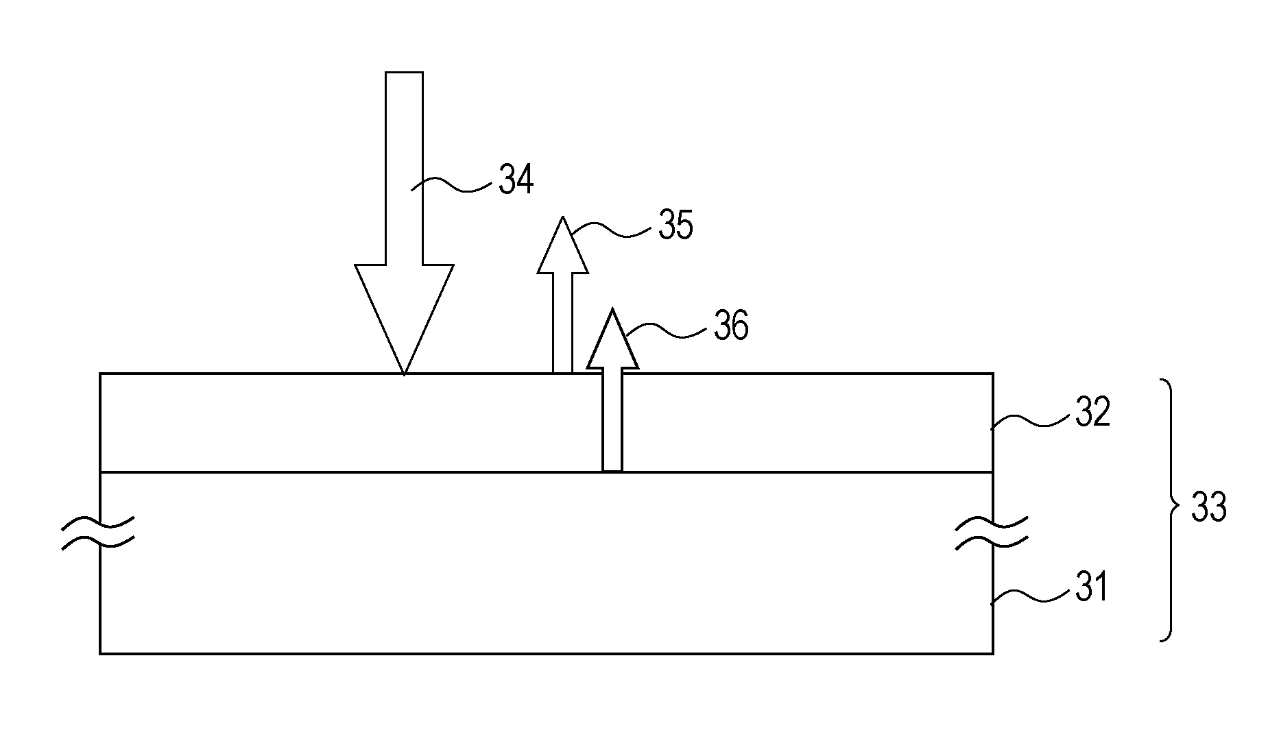
[0041]FIG. 1 illustrates reflectivity characteristics of an optical element provided with a thin film according to a first embodiment of the present invention. The horizontal axis plots wavelengths and the vertical axis plots reflectivities. Regarding the reflectivity characteristics of the optical element, a peak value of the reflectivity is located at a wavelength of 550 nm. The reflectivity at the peak value is 0.40%. Reflectivities with wavelengths of 400 nm and 700 nm at both ends of the usable wavelength range are respectively 0.15% and 0.28%.

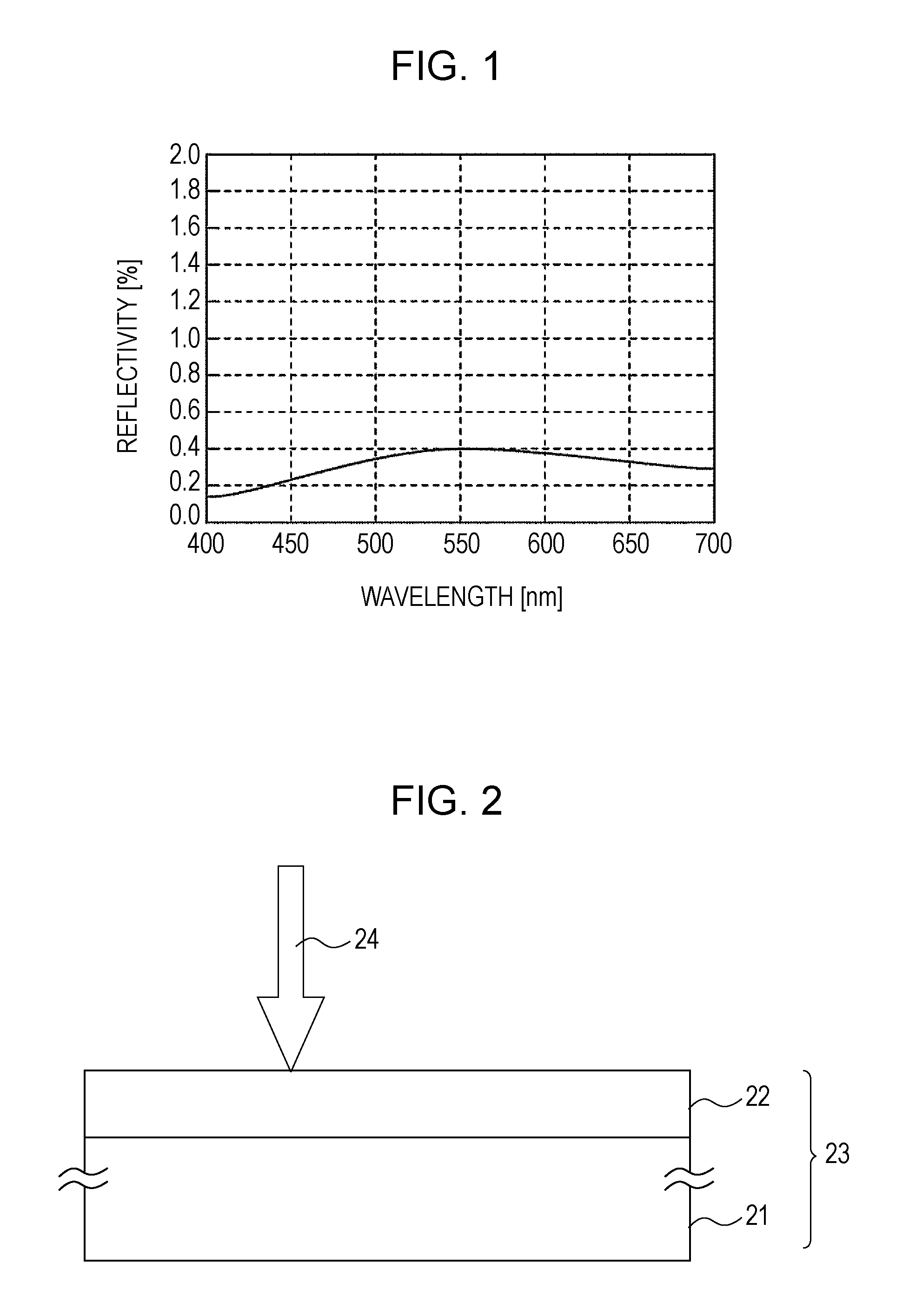
[0042]This embodiment illustrates a graded layer having a reflectivity that is gradually (i.e. continuously or progressively) decreased from the substrate side towards an outer surface of the graded layer. FIG. 2 illustrates an example of an optical structure provided with a thin film on a surface of a substrate. Reference numeral 21 denotes a substrate, 22 denotes a thin film, 23 denotes an optical element, and 24 denotes incident light....

second embodiment

[0061]FIG. 13 illustrates reflectivity characteristics according to a second embodiment of the present invention. The horizontal axis plots wavelengths and the vertical axis plots reflectivities. Regarding the characteristics, a peak value of the reflectivity is located at a wavelength of 500 nm. The reflectivity at the peak value is 0.18%. Reflectivities with wavelengths of 400 nm and 700 nm at both ends of the usable wavelength range are respectively 0.06% and 0.03%. The values satisfy all the aforementioned conditions (1) to (4).

[0062]The configuration of the second embodiment is shown in FIG. 12. Reference numeral 121 denotes a substrate, and 122 denotes a petaloid structure layer formed of a structure that is smaller than the wavelength of light to be used. The refractive index gradient of the structure layer is shown in FIG. 14. The substrate is a glass member with a refractive index of 1.583 for the d-line. Regarding the refractive index gradient, it is found that the refract...


PUM

PropertyMeasurementUnit
Fractionaaaaaaaaaa
Wavelengthaaaaaaaaaa
Optical reflectivityaaaaaaaaaa

Abstract

An optical element includes a substrate, and an antireflection film provided on a surface of the substrate. The antireflection film is a graded layer having a refractive index that is progressively decreased from the substrate side towards an outer surface of the antireflection film. The graded layer has a reflectivity characteristic occupying ⅔ of a usable wavelength range around the center of the usable wavelength range. Reflectivity of the graded layer at a maximum value of the reflectivity characteristic is a peak value equal to or less than 0.4% The graded layer does not have a maximal value not corresponding to the peak value. At least one of reflectivities at both ends of the usable wavelength range is equal to or less than half the reflectivity at the peak value.

Description

BACKGROUND OF THE INVENTION[0001]1. Field of the Invention[0002]The present invention relates to an optical element, an optical system including the optical element, and an optical apparatus including the optical system, and relates more particularly to optical characteristics of the optical element.[0003]2. Description of the Related Art[0004]When a beam of light impinges on the surface of a transparent material, such as glass, a fraction of the incident light is scattered (reflected) in all directions. The surface roughness of the material is responsible for this loss of energy. Accordingly, a member used in an optical part typically has an antireflection function. A transparent member without an antireflection function has a transmittance that is decreased by about 4% to 8% per surface. Therefore, in a system that uses a plurality of transparent members without an antireflection function, for example, in a photography optical system, the quantity of transmitting light can be mark...

Claims


Application Information

Patent Timeline
IPC IPC(8): G02B1/11G02B1/02G02B1/118
CPCG02B1/118G02B1/113G02B1/14
Inventor SANO, DAISUKE
Owner CANON KK
Why Eureka
Try Eureka