Organic light emitting diode display and method for manufacturing the same

a light-emitting diode and organic technology, applied in the field of active matrix type organic light-emitting diode display, can solve the problems of poor inability to fundamentally improve the emission coupling efficiency, and unclear whether the thin film transistor circuit can withstand high pressure or not, so as to reduce the coupling-out efficiency of emission from the organic electroluminescence layer to the outside, the effect of reducing the correlation between the film density and the light scatter

Active Publication Date: 2005-07-21
SAMSUNG DISPLAY CO LTD +1
View PDF0 Cites 50 Cited by
  • Summary
  • Abstract
  • Description
  • Claims
  • Application Information

AI Technical Summary

Benefits of technology

[0031] The porous insulating film according to the present invention has a feature that the maximal diameter of nano pores in the porous insulating film is not shorter than 0.3 nm and shorter than 2.0 nm. When the maximal diameter of nano pores is shorter than 0.3 nm, the diameter of nano pores is so small that the light scattering effect depending on the nano pores is reduced. As a result, the coupling-out efficiency of emission from the organic electroluminescence layer to the outside becomes poor. Thus, it is impossible to obtain an effect intended in the present invention. When the maximal diameter of nano pores is not shorter than 2.0 nm, the film density is reduced in correlation therewith. That is, the film physical property such as the film hardness or the coefficient of elasticity is lowered. Thus, it is difficult to say the insulating film is suitable for forming a thin film transistor circuit.
[0032] The porous insulating film according to the present invention has a feature that the light transparency in a visible light wavelength range is 80% or higher, more preferably 90% or higher. When the light transparency is lower than 80%, the light shielding effect surpasses the coupling-out effect of emission. Thus, it is impossible to obtain an effect intended in the present invention.
[0033] The porous insulating film having the aforementioned features (1) to (6) is lower in refractive index than the transparent substrate or the transparent electrode used in the OLED display. In addition, the porous insulating film also provides a light scattering effect due to nano pores existing in the film. Accordingly, light emitted from the organic electroluminescence layer is prevented from being confined in the transparent substrate or the transparent electrode so that the emission from the organic electroluminescence layer can be coupled out to the outside efficiently. Thus, the luminance can be improved.

Problems solved by technology

To apply the aforementioned background-art techniques to active matrix type OLED displays, there are problems as follows.
Such a structure is built because the coupling-out efficiency of emission cannot be fundamentally improved if there is no contact between the low-refractive body and the transparent electrode.
It can be, however, noted that the thin film transistor circuit cannot withstand the temperature.
However, this is also unclear as to whether the thin film transistor circuit can withstand the high pressure or not.

Method used


Image

  • Organic light emitting diode display and method for manufacturing the same
  • Organic light emitting diode display and method for manufacturing the same
  • Organic light emitting diode display and method for manufacturing the same

Examples


example 1

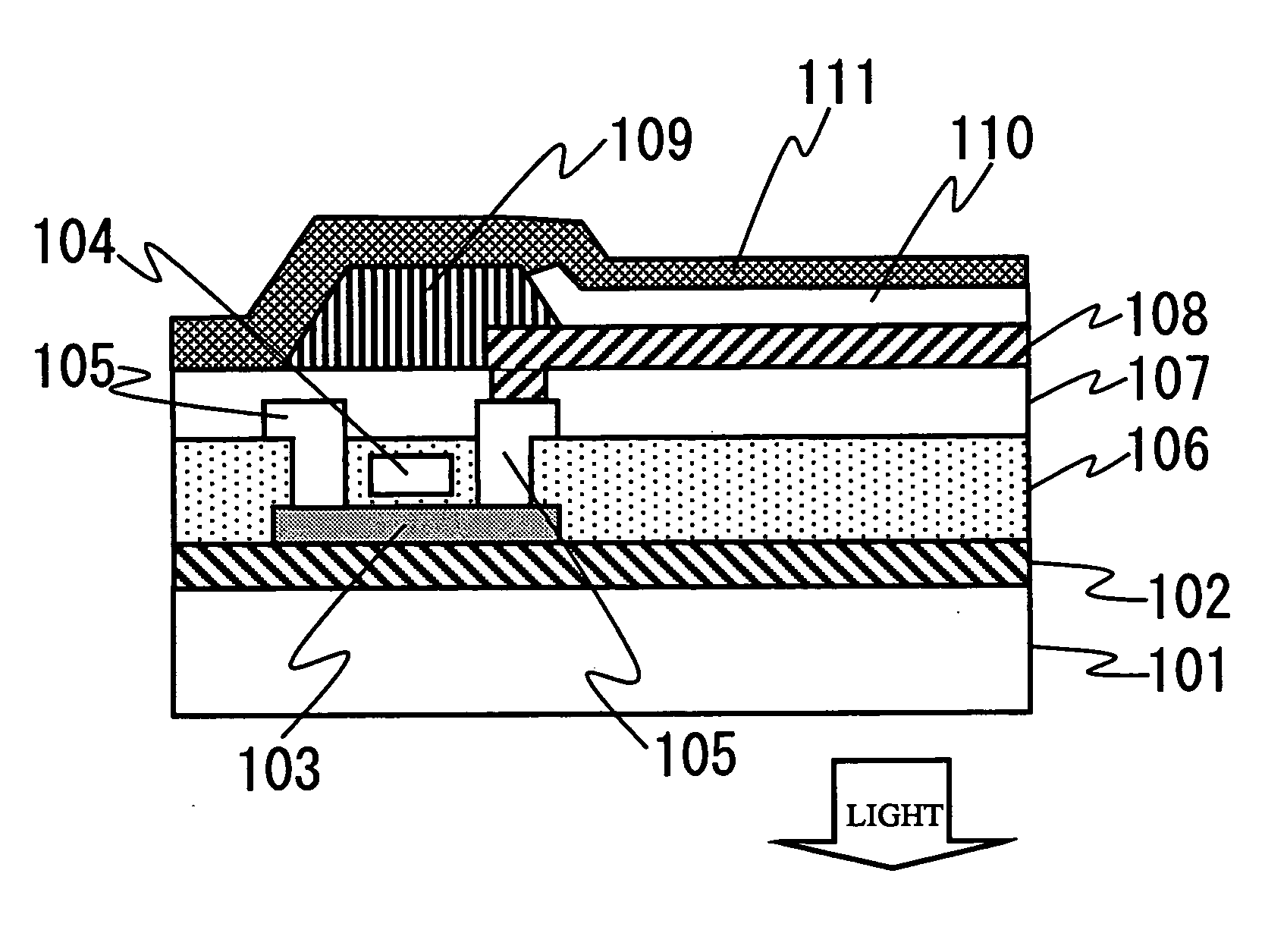
[0096] An OLED display whose sectional view is shown in FIG. 1 was manufactured in the following conditions. In FIG. 1, the undercoat insulator 102 was formed out of an SiN film 100 nm thick and an SiO film 50 nm thick thereon by a CVD method so as to have a total thickness of 150 nm. The interlayer insulator 106 was formed out of an SiO film 400 nm thick by use of a CVD method. The pixel separating insulator 109 was formed out of an SiN film 150 nm thick by use of a CVD method.

[0097] A methyl isobutyl ketone application solution containing a hydrogen silsesquioxane compound as its chief component was applied to a substrate as the insulator 107 contacting with the anode transparent electrode 108. After that, by use of a hot plate heating system, the substrate was heated at 100° C. for 10 minutes, at 150° C. for 10 minutes, at 230° C. for 10 minutes and at 350° C. for 10 minutes in an inert atmosphere such as a nitrogen atmosphere. Thus, Si—O—Si bonds were formed like a ladder struc...

example 2

[0116] A methyl isobutyl ketone application solution containing a methyl silsesquioxane compound as its chief component was applied to a substrate as the insulator 107 contacting with the anode transparent electrode 108. After that, by use of a hot plate heating system, the substrate was heated at 100° C. for 10 minutes, at 150° C. for 10 minutes, at 230° C. for 10 minutes and at 350° C. for 10 minutes in an inert atmosphere such as a nitrogen atmosphere. Thus, Si—O—Si bonds were formed like a ladder structure, and finally formed into a porous insulating film containing SiO as its chief component.

[0117] On this occasion, the porous insulating film had the following properties.

Film Thickness: 230 nm, Density: 1.25 g / cm3, Refractive Index: 1.30, Film Hardness: 4.6 GPa, Film Elasticity: 3.2 GPa, Average Nano Pore Diameter in Film: 2.3 nm

[0118] An OLED display was manufactured in the same conditions as in Example 1, except the aforementioned film. The OLED display was turned on in t...

example 3

[0121] A methyl isobutyl ketone application solution containing a hydrogen silsesquioxane compound different from that in Example 1 as its chief component was applied to a substrate as the insulator 107 contacting with the anode transparent electrode 108. After that, by use of a hot plate heating system, the substrate was heated at 100° C. for 10 minutes, at 150° C. for 10 minutes, at 230° C. for 10 minutes and at 350° C. for 10 minutes in an inert atmosphere such as a nitrogen atmosphere. Thus, Si—O—Si bonds were formed like a ladder structure, and finally formed into a porous insulating film containing SiO as its chief component.

[0122] On this occasion, the porous insulating film had the following properties.

Film Thickness: 230 nm, Density: 1.42 g / cm3, Refractive Index: 1.33, Film Hardness: 0.53 GPa, Film Elasticity: 6.7 GPa, Average Nano Pore Diameter in Film: 1.1 nm, Maximum Nano Pore Diameter in Film: 0.64 nm

[0123] An OLED display was manufactured in the same conditions as ...


PUM

PropertyMeasurementUnit
densityaaaaaaaaaa
densityaaaaaaaaaa
pore diameteraaaaaaaaaa

Abstract

An active matrix type organic light emitting diode display serving as a bottom emission type device coupling out emission of an organic electroluminescence layer from a substrate where thin film transistors are formed or as a top emission type device coupling out the emission on the opposite side to the substrate. In a suitable layer (102, 106, 107) in each device, an insulating film containing SiO is formed. The insulating film is porous with nano pores in the film. The porous insulating film is controlled as to film density, film refractive index, nano pore diameter in film, average nano pore diameter in film and maximum nano pore diameter in film so that the refractive index is lower than that of a transparent electrode or a transparent substrate of the display holding the organic electroluminescence layer therebetween, and nano pores are present in the film. Light scattering effect can be obtained so that emission from the organic electroluminescence layer (110) can be coupled out to the outside efficiently.

Description

BACKGROUND OF THE INVENTION [0001] The present invention relates to an active matrix type organic light emitting diode display, and particularly relates to a high-performance active matrix type organic light emitting diode display in which the coupling-out efficiency of emission from an organic electroluminescence layer is improved, and a method for manufacturing the same. [0002] An organic light emitting diode (hereinafter referred to as “OLED”) display is a self-emitting device different from a liquid crystal display needing a backlight. Accordingly, the OLED display is characterized in that it is thin in profile, wide in viewing angle, high in response speed and hence excellent in movie display in comparison with the liquid crystal display. In recent years, OLED displays have been researched and developed actively, and announcements of product planning have been made extensively. [0003] A fundamental structure of an OLED display is a sandwich structure in which an OLED emission l...

Claims


Application Information

Patent Timeline
Patent Type & Authority Applications(United States)
IPC IPC(8): C09K11/00H05B33/22C09K11/06G09F9/30H01L27/32H01L51/52H05B33/00H05B33/06H05B33/10H05B33/12H05B33/14H05B33/26
CPCH01L27/3244H01L51/5268H01L51/5262H10K59/12H10K50/85H10K50/854H05B33/22H05B33/10
Inventor TANAKA, JUNOGATA, KIYOSHIADACHI, MASAYAOTANI, MIHARU
Owner SAMSUNG DISPLAY CO LTD
Why Eureka
Try Eureka