This helps you quickly interpret patents by identifying the three key elements:
Problems solved by technology
Method used
Benefits of technology
Benefits of technology
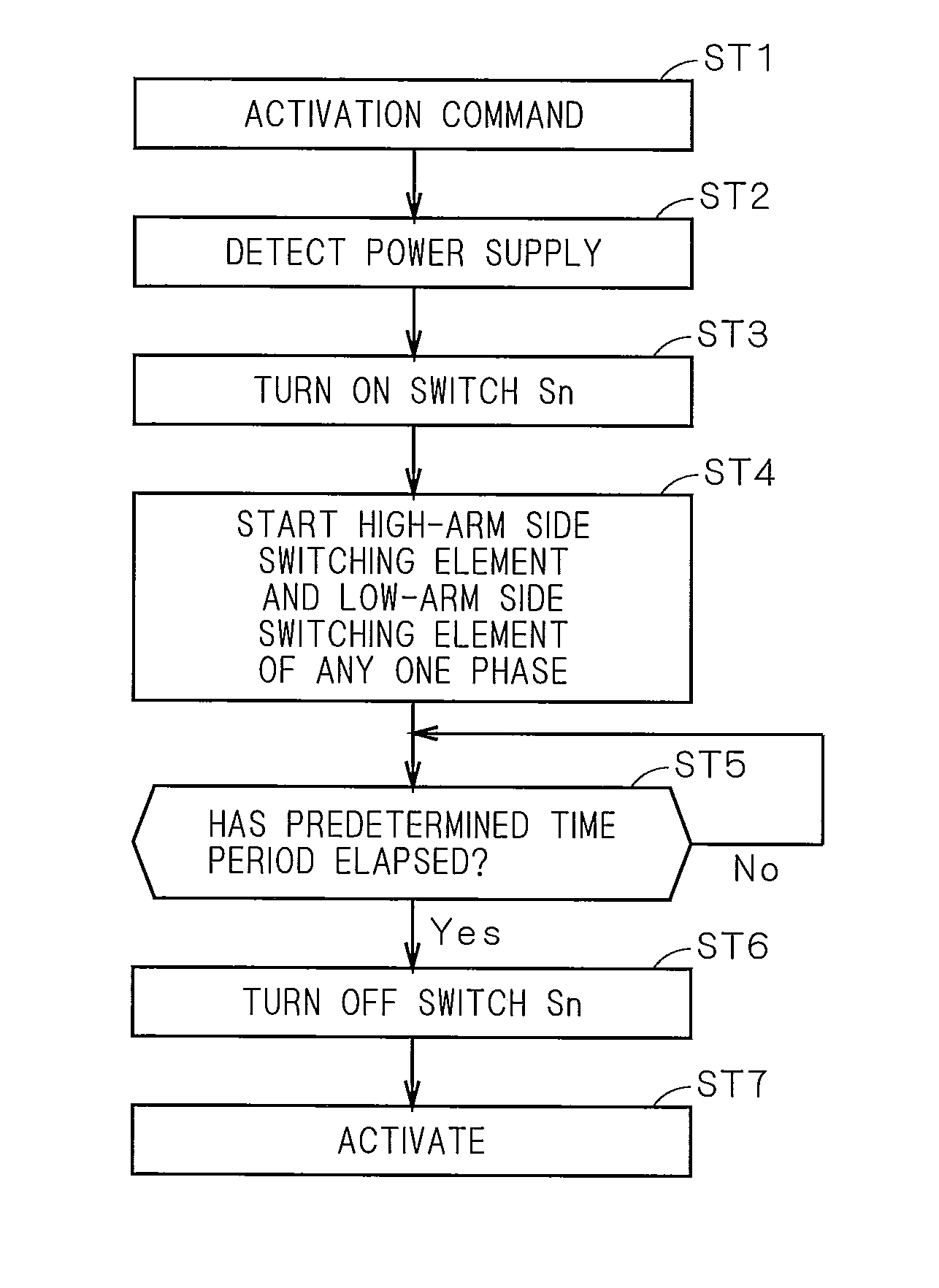
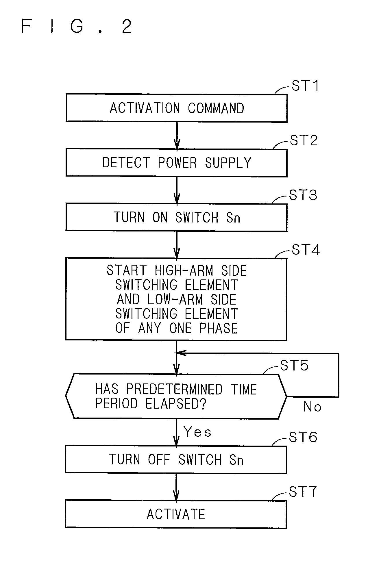
[0023]In the first aspect of the direct AC power converting apparatus according to the present invention, an inrush current is prevented from flowing from the multi-phase AC power source to the first capacitor and the second capacitor at a time of an initial operation of the current-source power converter. At this time, the input capacitor is not electrically connected to the first capacitor and the second capacitor.
[0024]When a pair of the high-arm side switching element and the low-arm side switching element which are connected to one input line is rendered conducting while the switch is conducting, the current-source power converter, together with the neutral phase input line, the first capacitor, and the second capacitor, equivalently forms a voltage doubler rectification circuit. Therefore, a voltage between both ends of a pair of the first capacitor and the second capacitor after being charged has a value twice as high as a voltage value of the multi-phase AC power source.
[0025]After the switch is rendered non-conducting, the current-source power converter converts a multi-phase AC current flowing among the input lines into a DC current, and supplies the DC current to the first capacitor and the second capacitor. Therefore, the input capacitor is connected in parallel with the first capacitor and the second capacitor. A voltage between both ends of the input capacitor corresponds to a line voltage of the input line, and has a value √3 as high as a voltage value of the multi-phase AC power source.
[0026]The voltage between both ends of a pair of the first capacitor and the second capacitor is higher than the voltage between both ends of the input capacitor. Therefore, an inrush current can be effectively prevented from flowing from the input capacitor to the first capacitor and the second capacitor in a case where the input capacitor is connected in parallel with the first capacitor and the second capacitor. In the second aspect of the direct AC power converting apparatus according to the present invention, the resistor is provided on the neutral phase input line. Therefore, by using any input line, the DC current can be supplied to the first capacitor and the second capacitor via the resistor.
[0027]In the third aspect of the direct AC power converting apparatus according to the present invention, a carrier current component removal filter that removes a carrier current component can be formed with the reactor and the input capacitor. Additionally, since the resistor and the reactor are connected in parallel, voltage pulsations of the input capacitor, which may occur at an initial stage of charging (at a transient time), can be reduced.
[0028]In the fourth aspect of the direct AC power converting apparatus according to the present invention, the first capacitor and the second capacitor are charged in a series-connection state and discharged in a parallel-connection state, due to a rectifying function of the first to third diodes. The first capacitor and the second capacitor are charged with a regenerative current from the inductive multi-phase load, and discharged when a voltage between both ends of each of the first and second capacitor exceeds a voltage value determined based on a load power factor at the voltage-source power converting apparatus side. That is, since a discharging path can be ensured by using the first capacitor and the second capacitor, an operation equivalent to the operation of the mode disclosed in Lixiang Weigh, and Thomas A. Lipo, “Investigation of 9-switch Dual-bridge Matrix Converter Operating under Low Output Power Factor”, U.S.A., IEEE ISA2003, vol. 1, pp. 176-181 can be realized even though the path is a passive circuit.
Image
Click on the blue label to locate the original text in one second.
Reading with bidirectional positioning of images and text.
Examples
first embodiment
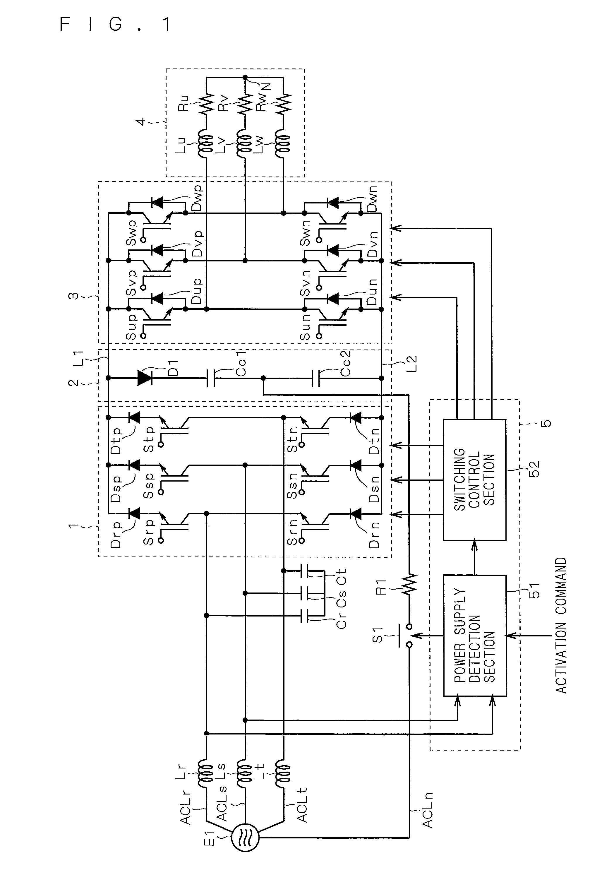
[0044]As an example of a direct AC power converting apparatus according to a first embodiment of the present invention, a conceptual configuration of a motor driving device is shown in FIG. 1. The motor driving device includes a power source E1, input lines ACLr, ACLs, ACLt, a neutral phase input line ACLn, reactors Lr, Ls, Lt, capacitors Cr, Cs, Ct, a current-source converter 1, DC power supply lines L1, L2, a clamp circuit 2, a voltage-source inverter 3, a motor 4, a control section 5, a resistor R1, and a switch S1.
[0045]The power source E1 is a multi-phase AC power source having a neutral point (not shown), and for example, is a three-phase AC power source. An output of the power source E1 is given to the input lines ACLr, ACLs, ACLt.
[0046]The reactors Lr, Ls, Lt are provided on the input lines ACLr, ACLs, ACLt, respectively.
[0047]The capacitors Cr, Cs, Ct are provided among the respective input lines ACLr, ACLs, ACLt, by being Y-connected with one another, for example. Specific...
second embodiment
[0090]As an example of a direct AC power converting apparatus according to a second embodiment, a conceptual configuration of a motor driving device is shown in FIG. 8. The conceptual configuration of the present motor driving device is the same as that of the motor driving device shown in FIG. 7, except for resistors R1 to R3 and an auxiliary switch Sr. In FIG. 8, illustration of the circuits in stages subsequent to the clamp circuit 2 is omitted. A mode of the clamp circuit 2 may be the one shown in FIG. 1.
[0091]The resistors R1 to R3 are inserted in the input lines ACLr, ACLs, ACLt, respectively. The auxiliary switch Sr is connected in series with any of the reactors Lr to Lt. In an exemplary mode illustrated in FIG. 8, the auxiliary switch Sr is connected in series with the reactor Lr. The reactors Ls, Lt are connected in parallel with the resistors R2, R3, respectively. A pair of the auxiliary switch Sr and the reactor Lr are connected in parallel with the resistor R1.
[0092]The...
PUM
Abstract
A control section controls a current-source converter while a switch is conducting, to render conducting a pair of a high-aim side transistor and a low-arm side transistor (for example, transistors) which are connected to any one of input lines, performs voltage doubler rectification on a voltage between a neutral phase input line on which a resistor is provided and any one of the input lines, to serve for charging of clamp capacitors.
Description
TECHNICAL FIELD[0001]The present invention relates to a direct AC power converting apparatus, and particularly to a technique for preventing an inrush current to a capacitor included in the direct AC power converting apparatus.BACKGROUND ART[0002]Lixiang Weigh, and Thomas A. Lipo, “Investigation of 9-switch Dual-bridge[0003]Matrix Converter Operating under Low Output Power Factor”, U.S.A., TREE ISA2003, vol. 1, pp. 176-181 which will be described later discloses a direct AC power converting apparatus including a clamp circuit. FIG. 12 shows the direct AC power converting apparatus disclosed in the Lixiang Weigh, and Thomas A. Lipo, “Investigation of 9-switch Dual-bridge Matrix Converter Operating under Low Output Power Factor”, U.S.A., IEEE ISA2003, vol. 1, pp. 176-181.[0004]For the convenience of description in the present application, the reference characters in the figure do not always coincide with those in the Lixiang Weigh, and Thomas A. Lipo, “Investigation of 9-switch Dual-b...
Claims
Application Information
Patent Timeline
Application Date:The date an application was filed.
Publication Date:The date a patent or application was officially published.
First Publication Date:The earliest publication date of a patent with the same application number.
Issue Date:Publication date of the patent grant document.
PCT Entry Date:The Entry date of PCT National Phase.
Estimated Expiry Date:The statutory expiry date of a patent right according to the Patent Law, and it is the longest term of protection that the patent right can achieve without the termination of the patent right due to other reasons(Term extension factor has been taken into account ).
Invalid Date:Actual expiry date is based on effective date or publication date of legal transaction data of invalid patent.

