
Electrical connector

a technology of electrical connectors and connectors, applied in the direction of coupling device details, coupling contact members, coupling device connections, etc., can solve the problems of increasing the difficulty of assembling, reducing the efficiency of stamping and assembling, and waste of materials, so as to avoid pin damage to the chip module as well as the conductive terminal, reduce processing procedures such as bending, and improve the effect of electrical connection

Active Publication Date: 2010-11-25
LOTES
View PDF8 Cites 18 Cited by
  • Summary
  • Abstract
  • Description
  • Claims
  • Application Information

AI Technical Summary

Benefits of technology

[0017]Therefore it is a primary object of the present invention to provide an electrical connector that provides good electrical connection among a conductive terminal, chip module and a circuit board. Moreover, the design of the electrical connector is easily assembled and material saving.
[0018]Moreover, it is another object of the present invention to provide an electrical connector in which a conductive terminal has higher elasticity so as to provide better hold and contact.

Problems solved by technology

Although the above conductive terminal solves the problems of damages of pins as well as the conductive terminal, such design still has some disadvantages:1. Considering the cost, the material is wasted because the two arms are totally formed by material on left and right sides of the base and then being bent inwards.
This increases the level of difficulty in assembling and reduces the efficiency of stamping as well as assembling.
Thus the manufacturing cost is increased.

Method used


Image

  • Electrical connector
  • Electrical connector
  • Electrical connector

Examples


Embodiment Construction

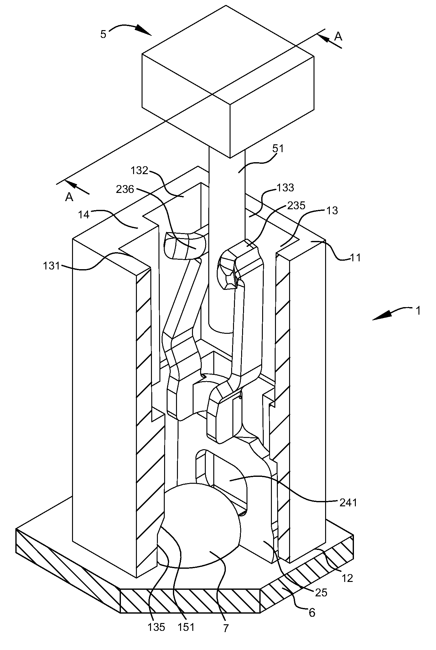
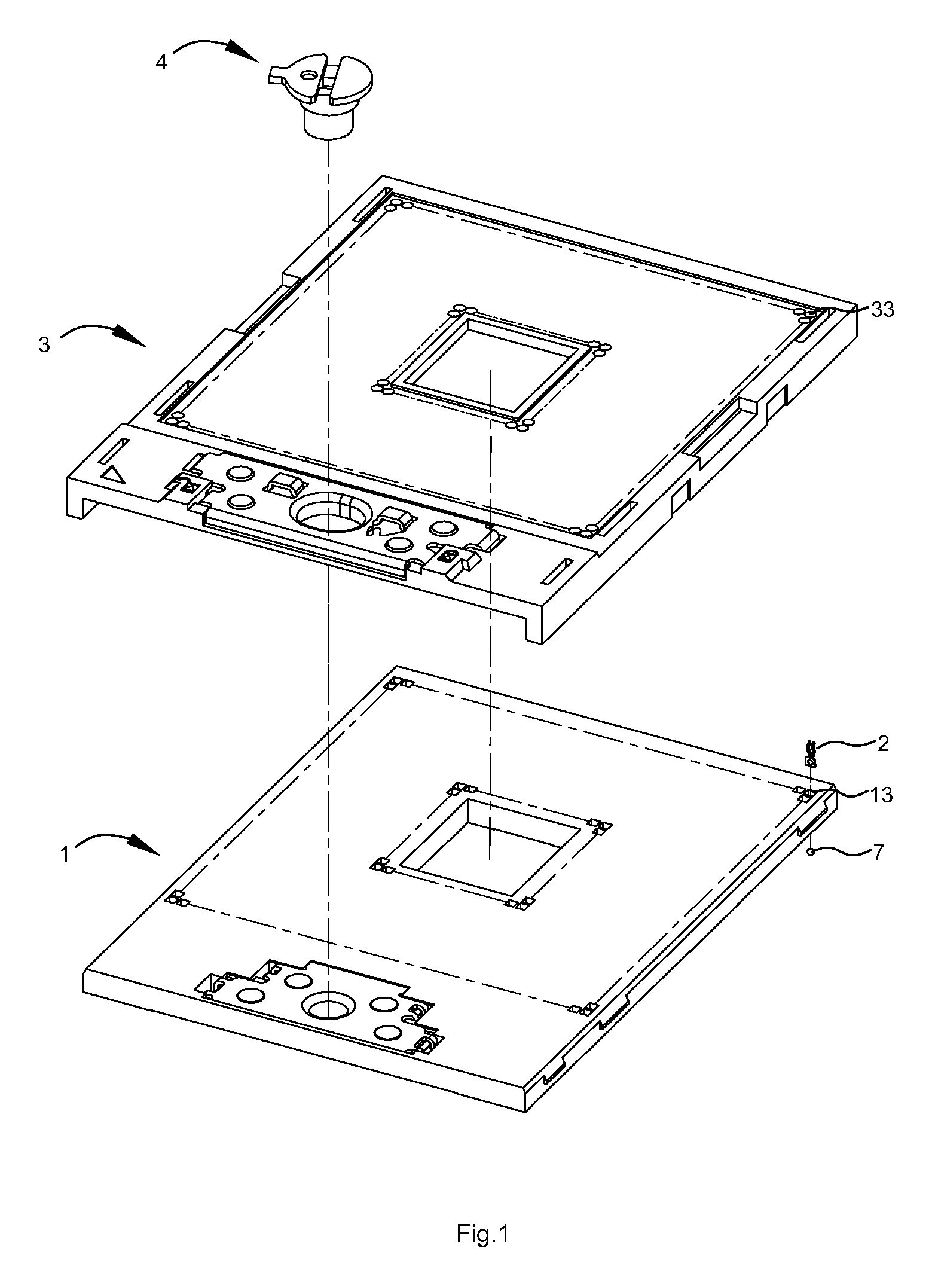
[0035]Refer to FIG. 1, an electrical connector of the present invention includes an insulative body 1, a plurality of conductive terminals 2 fixed in the insulative body 1, a top cover 3 that being sliable over the insulative body 1, and a driving member 4 that drives the top cover 3 to slide along the insulative body 1.

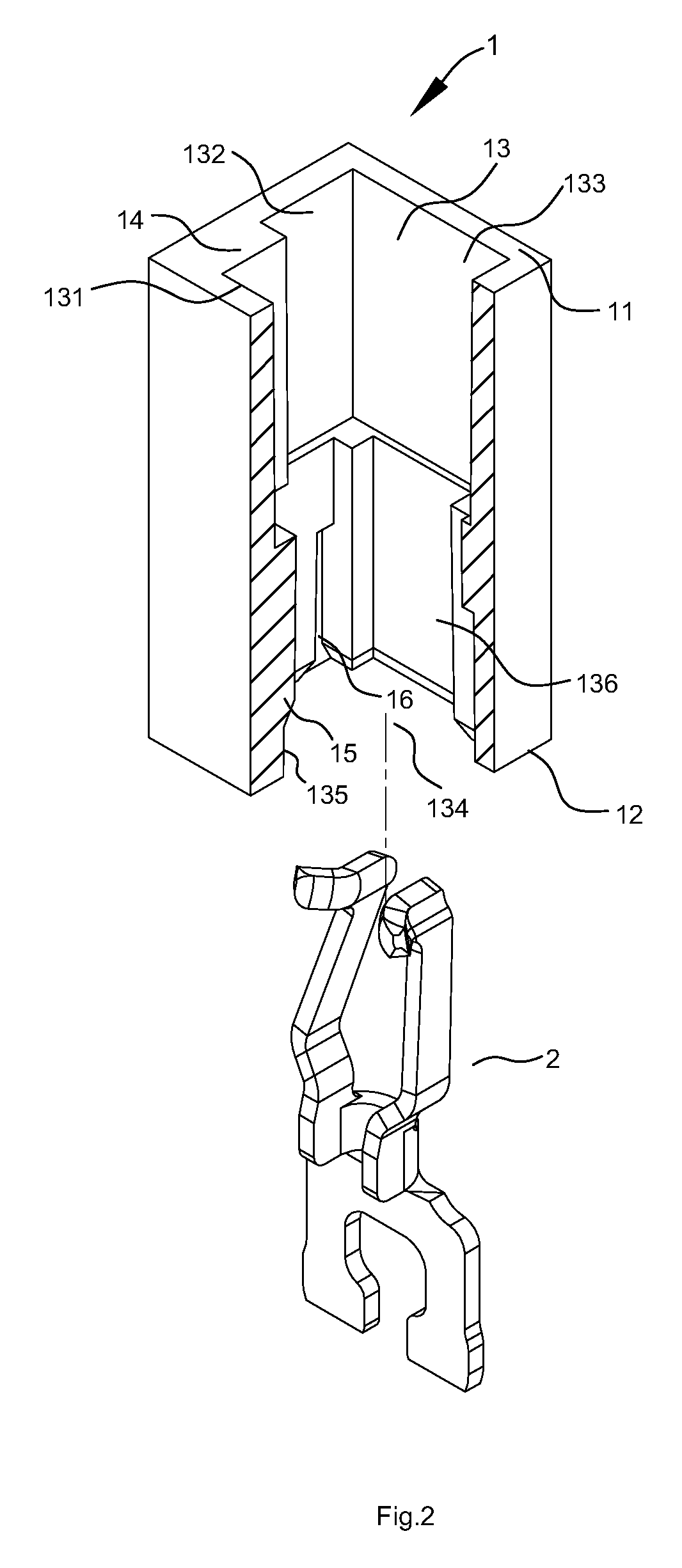
[0036]Refer to FIG. 2, the insulative body 1 has an upper surface 11 and a lower surface 12 arranged corresponding to each other, and a plurality of terminal receiving slots 13 penetrating the upper surface 11 and the lower surface 12.

[0037]The terminal receiving slot 13 is composed of a first side wall 131, two second side walls 132 beside the first side wall 131, a third side wall 133 beside the second side wall 132. The first side wall 131 and the third side wall 133 are disposed opposite to each other. Moreover, a receiving space 134 is formed at one end of the terminal receiving slot 13, near the lower surface 12.

[0038]A projecting block 14 is disposed projectin...


PUM


Abstract

Disclosed is an electrical connector including a plurality of conductive terminals. The conductive terminal comprises a base and a pair of arms. Each arm includes a connection part extending forwardly from the base, a first bending part bent and extending upwardly from the connection part, a second bending part bent upwardly from the first bending part, a first elastic arm extending upwardly from the second bending part, and a contact section formed at a rear end of the first elastic arm. The first and second bending part are bent away from the other arm while the first elastic arm extends toward the other arm. The minimum distance between the two first elastic arms and that between the two second bending parts are larger than the minimum distance between the two connection parts and that between the two contact sections.

Description

BACKGROUND OF THE INVENTION[0001]1. Field of Invention[0002]The present invention relates to an electrical connector, especially to an electrical connector that connects chip modules with circuit boards.[0003]2. Description of Related Art[0004]Along with prosperous development of electronic industries, electrical connectors have become more important and with broader applications in this field. Thus there are two important factors for people in this field to select proper electrical connectors-performance and cost of the electrical connector. Some other issues are also taken into considerations such as how to provide better electrical connection between the terminals of the electrical connector and electronic components / circuit boards, how to reduce cost of electrical connectors and improved manufacturing efficiency, and factors that affect performance or cost of the electrical connector. One of the factors is the shape and structure of the terminal of the electrical connectors.[000...

Claims


Application Information

Patent Timeline
Patent Type & Authority Applications(United States)
IPC IPC(8): H01R13/629
CPCH01R13/112H01R13/2485H01R13/2435
Inventor JU, TED
Owner LOTES
Learn More