Radio transmission device, method for determining modulation system, and recording medium therefor

Inactive Publication Date: 2010-11-25
NEC CORP
View PDF10 Cites 11 Cited by
  • Summary
  • Abstract
  • Description
  • Claims
  • Application Information

AI Technical Summary

Benefits of technology

[0019]According to this invention, it is possible to prevent a loss of signal from occurring d

Problems solved by technology

However, if the modulation scheme exhibiting a large fluctuation immunity in the radio transmission path is employed, the transmission capacity is reduced.
However, in a case where the adaptive modulation scheme for performing switching judgment only based on the received power is applied to the radio transmission device for transmitting/receiving continuous signals, if an instantaneous interruption in the received power occurs due to fading or the like, the modulation scheme is erroneously switched over, leading to a problem that a loss of signal occurs due to the switching.
In addition, in a c

Method used


Image

  • Radio transmission device, method for determining modulation system, and recording medium therefor
  • Radio transmission device, method for determining modulation system, and recording medium therefor
  • Radio transmission device, method for determining modulation system, and recording medium therefor

Examples


first exemplary embodiment

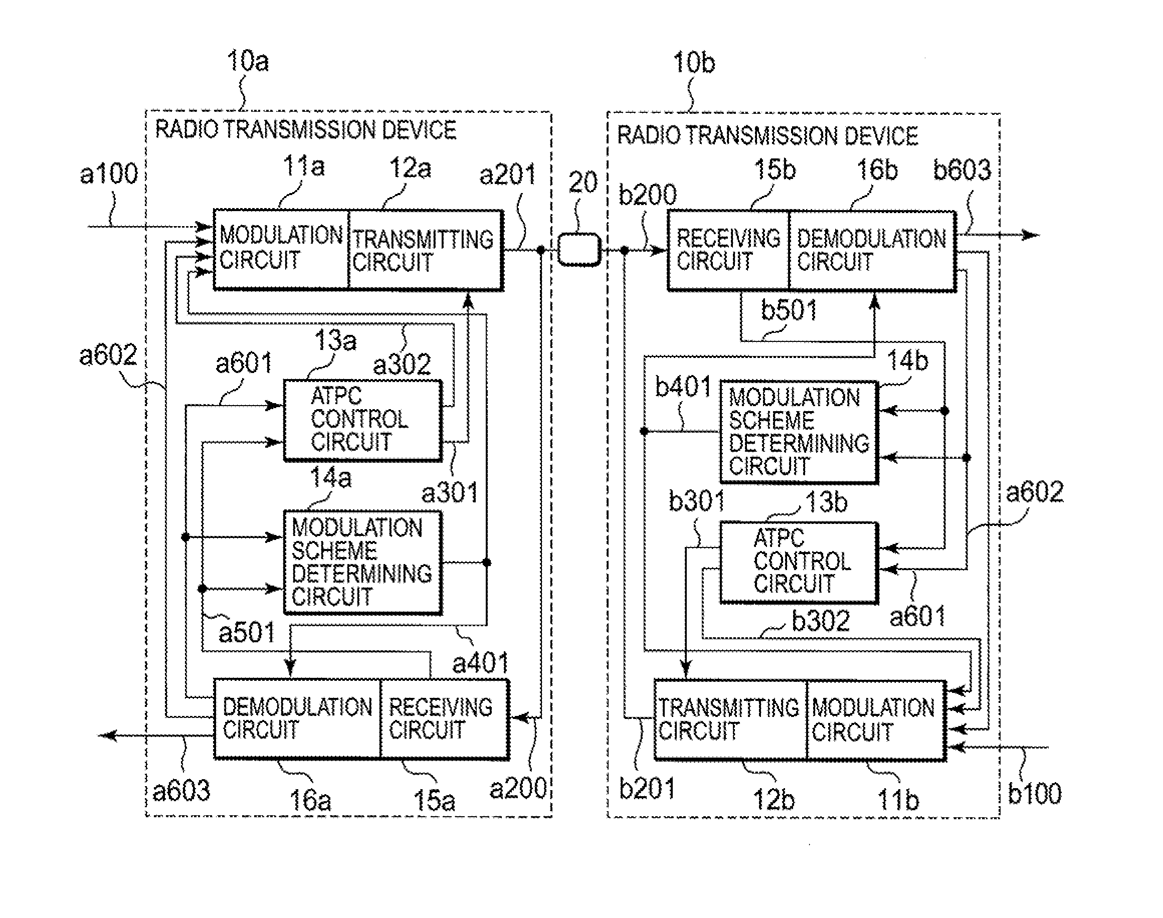
[0029]Referring to FIG. 1, description is made of a configuration of a radio transmission device according to a first exemplary embodiment of this invention. FIG. 1 is a block diagram illustrating a radio transmission system including a first radio transmission device 10a and a second radio transmission device 10b connected to each other via a radio transmission path 20.

[0030]By referring to FIG. 1, the first radio transmission device 10a according to the first exemplary embodiment of this invention includes a first modulation circuit 11a, a first transmitting circuit 12a, a first ATPC control circuit 13a, a first modulation scheme determining circuit 14a, a first receiving circuit 15a, and a first demodulation circuit 16a. In the same manner, the second radio transmission device 10b according to the first exemplary embodiment of this invention includes a second modulation circuit 11b, a second transmitting circuit 12b, a second ATPC control circuit 13b, a second modulation scheme d...

second exemplary embodiment

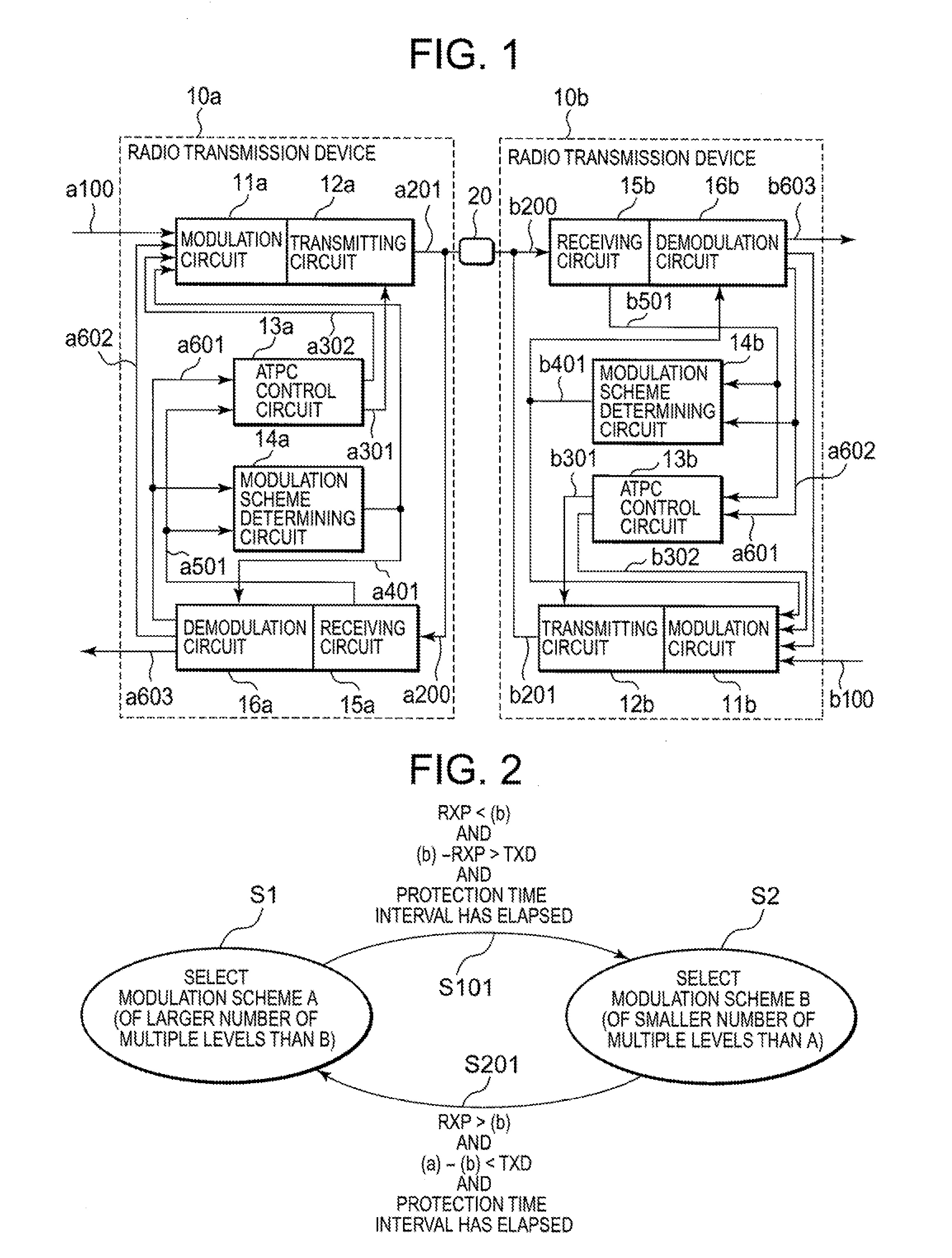
[0093]In the first exemplary embodiment illustrated in FIG. 1, the modulation scheme between the transmission / reception is determined by the modulation scheme determining circuit of the radio transmission device on a receiving end. Meanwhile, a second exemplary embodiment illustrated in FIG. 5 is configured so that the modulation scheme between the transmission / reception can be determined also by the modulation scheme determining circuit of the radio transmission device on a transmitting end.

[0094]Referring to FIG. 5, description is made of a configuration and an operation of a radio transmission device according to the second exemplary embodiment. FIG. 5 is a block diagram illustrating a radio transmission system including a first radio transmission device 10a and a second radio transmission device 10b connected to each other via a radio transmission path 20.

[0095]By referring to FIG. 5, the first radio transmission device 10a according to the exemplary second embodiment of this in...


PUM


Abstract

A problem that a loss of signal occurs due to switching of a modulation scheme using an adaptive modulation scheme is solved. A radio transmission device (10a, 10b) having an automatic transmission power control function of controlling transmission power of its own station so as to maintain received power of a counter station at a preset constant value and a function of an adaptive modulation scheme for automatically switching over a modulation scheme depending on quality of a radio transmission path includes a modulation scheme determining circuit (14a, 14b) for switching over the modulation scheme by using the adaptive modulation scheme in consideration of a transmission power margin and the received power.

Description

TECHNICAL FIELD[0001]This invention relates to a radio transmission device having an automatic transmission power control function (automatic transmitter power control (ATPC)) of controlling transmission power of its own station so as to maintain received power of a counter station at a preset constant value and a function of an adaptive modulation scheme for automatically switching over a modulation scheme depending on quality of a radio transmission path.BACKGROUND ART[0002]Signal transmission quality of a radio communication system depends on a situation of a radio transmission path. Therefore, received power during a normal operation is set higher than the received power of which minimum quality can be secured. As a result, a fluctuation immunity in the radio transmission path is small in a normal state. However, in the normal state, a modulation scheme of more multiple levels can be selected, which can enhance a transmission capacity.[0003]Meanwhile, even in a state in which th...

Claims


Application Information

Patent Timeline
IPC IPC(8): H04B1/04
CPCH04L1/0003H04L1/0018H04W52/262H04L27/0012H04L27/0008
Inventor NAKAJIMA, HIROAKI
Owner NEC CORP
Why Eureka
Try Eureka