Current Position Determining Device and Current Position Determining Method

a current position and lane change technology, applied in navigation instruments, instruments, transportation and packaging, etc., can solve the problems of inability to accurately determine the traveling lane, the lane change may not be detected by the camera, etc., and achieve the effect of improving the accuracy of determining the position

Active Publication Date: 2010-11-25
CLARION CO LTD
View PDF25 Cites 52 Cited by
  • Summary
  • Abstract
  • Description
  • Claims
  • Application Information

AI Technical Summary

Benefits of technology

[0005]It is an object of the present invention to provide a technology capable of improving the accuracy of determining a position of an own vehicle in the vicinity of a branch point; in a current position determining device.

Problems solved by technology

However, when the vehicle is traveling on a road having a section in which the lane change is permitted is longer than the predetermined uniform detection range, and makes a lane change outside the detection range, the lane change may not be detected by the camera, and the traveling lane may not be correctly determined.

Method used


Image

  • Current Position Determining Device and Current Position Determining Method
  • Current Position Determining Device and Current Position Determining Method
  • Current Position Determining Device and Current Position Determining Method

Examples


Embodiment Construction

[0019]In the following, a description is given of a navigation device 100 which is an on-board current position determining device mounted on a vehicle, to which an embodiment of the present invention is applied.

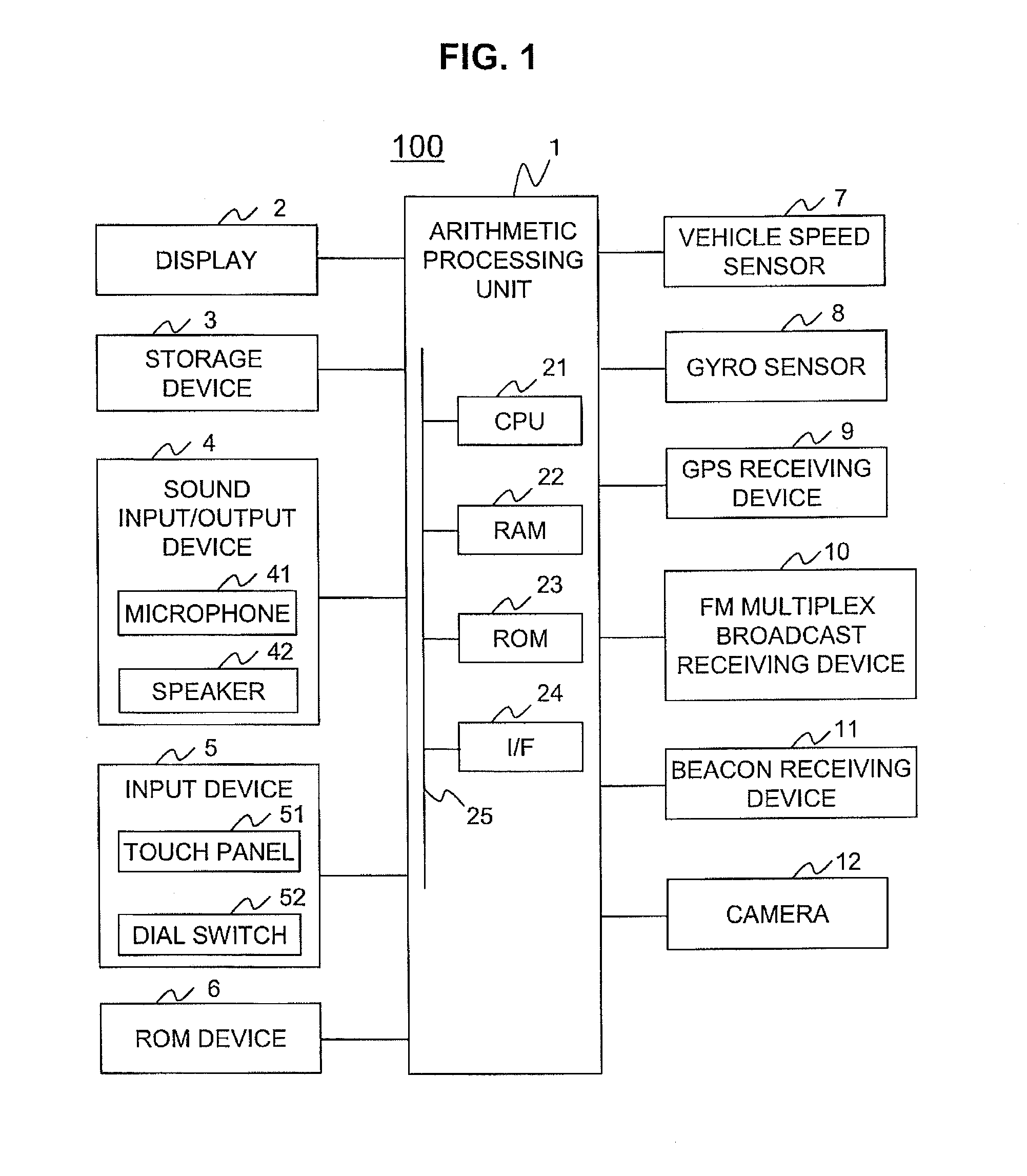
[0020]FIG. 1 is a configuration diagram of the navigation device 100.

[0021]The navigation device 100 includes an arithmetic processing unit 1, a display 2, a storage device 3, a sound input / output device 4 (which includes a microphone 41 as a sound input device and a speaker 42 as a sound output device 42), an input device 5, a ROM device 6, a vehicle speed sensor 7, a gyro sensor 8, a global positioning system (GPS) receiving device 9, an FM multiplex broadcast receiving device 10, a beacon receiving device 11, and a camera 12.

[0022]The arithmetic processing unit 1 is a central unit which carries out various kinds of processing. For example, the arithmetic processing unit 1 detects, based on information output from the various types of sensors 7 and 8, the GPS receiving dev...


PUM


Abstract

Provided is a technology capable of improving the accuracy of determining a position of an own vehicle in the vicinity of a branch point, in a current position determining device. The current position determining device identifies a detection range according to states of a road on which a vehicle is traveling to detect a lane change, to thereby determine a current position of the vehicle based on information on the detected lane change.

Description

INCORPORATION BY REFERENCE[0001]The present application claims a priority from Japanese application no. 2009-122695 filed on May 21, 2009, the content of which is hereby incorporated by reference into this application.BACKGROUND OF THE INVENTION[0002]The present invention relates to a technology of determining a current position.[0003]Conventionally, a navigation device estimates and determines a current position of an own vehicle, based on a traveling direction and a traveling speed from a position traveled in past. However, a vehicle travels in a branch such as a branch with a narrow Y shape, there is a problem of a decrease in accuracy of determining the own vehicle position. In order to solve this problem, there is a technology of detecting a traveling lane using a camera. Japanese Patent Application Laid-open No. 2005-322166 describes a technology for a navigation device as described above.SUMMARY OF THE INVENTION[0004]On the navigation device as described above, a load imposed...

Claims


Application Information

Patent Timeline
Patent Type & Authority Applications(United States)
IPC IPC(8): G01C21/26
CPCG06K9/00798G01C21/30G06V20/588
Inventor NAKAMURA, JUNYASAKAI, YOSHIKAZUMATSUMOTO, SHINJIUEMURA, MAKOTOYAMAMOTO, KENSUKE
Owner CLARION CO LTD
Why Eureka
Try Eureka