Caulking die and braid fixing structure for shield wire

a fixing structure and shield wire technology, applied in cable junctions, manufacturing tools, transportation and packaging, etc., can solve the problems of insufficient fixing force, poor workability, complex structure of the core, etc., and achieve the effect of satisfying shielding performance, preventing fraying in the braid end part, and increasing the fixing force for connection and fixing the braid end par

Active Publication Date: 2010-12-02
YAZAKI CORP
View PDF15 Cites 9 Cited by
  • Summary
  • Abstract
  • Description
  • Claims
  • Application Information

AI Technical Summary

Benefits of technology

[0018]According to the present invention having such features, by virtue of the two-ply structure in the braid end part, the mesh of the braid connected and fixed to the braid holding part becomes dense. Thus, even when the braid end part is spread and inserted over the braid holding part, the shielding performance is achieved satisfactorily. Further, the two-ply structure in the braid end part avoids the necessity of after treatment such as cutting a pointed end part in the braid end part. Furthermore, the two-ply structure in the braid end part contributes to prevention of fraying in the braid end part.
[0019]The present invention described in the first aspect of the invention has the effect of providing a caulking die in which even when caulking is performed such that a protruding rim is generated that protrudes from the inner peripheral surface of the braid holding part to the circumferential direction, extraction of the core is allowed. Further, the use of this caulking die has an effect that the fixing force for connection and fixation of the braid end part is increased satisfactorily.
[0020]According to the present invention described in the second aspect of the invention, a caulking die is employed in which even when caulking is performed such that a protruding rim is generated that protrudes from the inner peripheral surface of the braid holding part to the circumferential direction, extraction of the core is allowed. Thus, an effect is obtained that the fixing force for connection and fixation of the braid end part is satisfactorily increased structurally.
[0021]The present invention described in the third aspect of the invention has an effect that the inclined structure allows the core to be extracted easily from the braid holding part.
[0022]According to the present invention described in the fourth aspect of the invention, the two-ply structure is formed in the braid end part so that the braid density is increased. This provides the effect of improving the shielding performance. Another effect is also obtained that the necessity of after treatment for the braid end part is avoided so that the workability is improved and the cost is reduced. Yet another effect is obtained that fraying in the braid end part is avoided.

Problems solved by technology

When the core constructed as an integration of a plurality of components is employed, problems arise that the core has a complicated structure and that poor workability is caused in association with the extraction of the core after the caulking.
This approach effectively resolves the above-mentioned problem, but causes another problem of an insufficient fixing force.

Method used


Image

  • Caulking die and braid fixing structure for shield wire
  • Caulking die and braid fixing structure for shield wire
  • Caulking die and braid fixing structure for shield wire

Examples


embodiment 1

[0030]A first embodiment is described below with reference to the drawings. FIG. 1 is a diagram showing a braid fixing structure for shield wire and a caulking die according to the present invention.

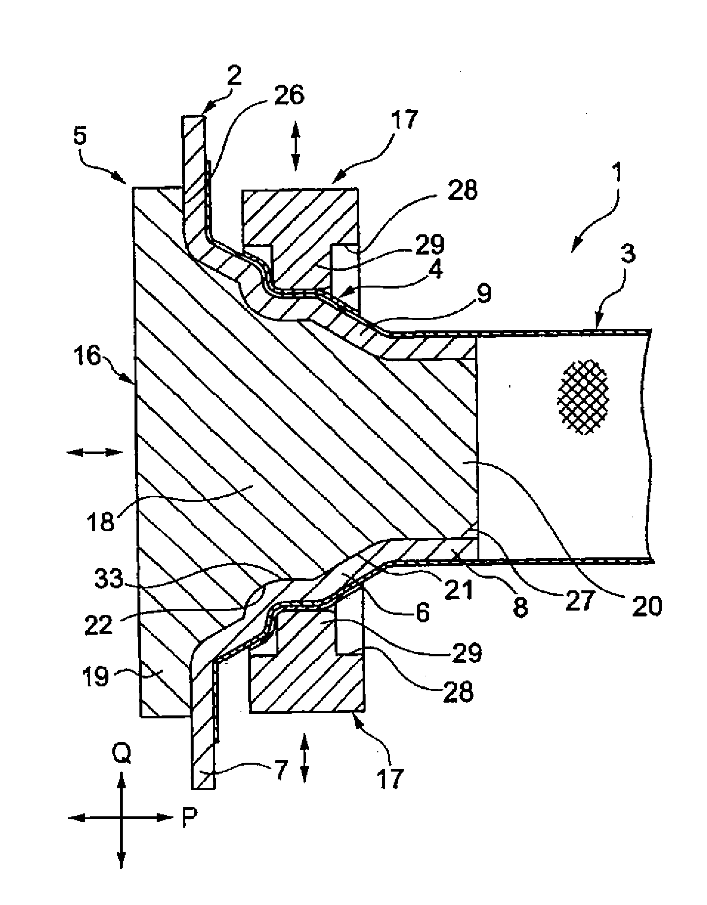
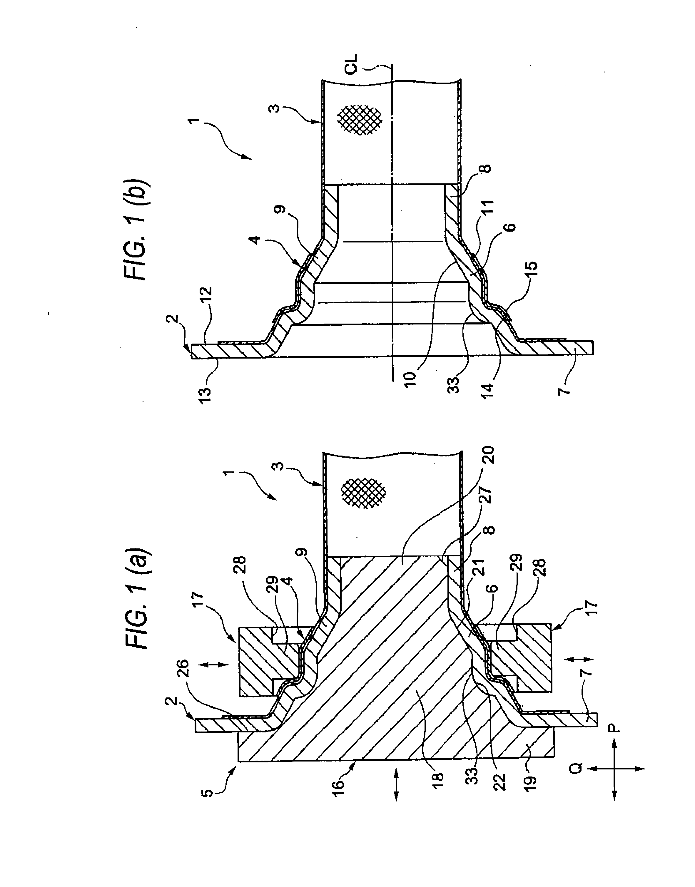
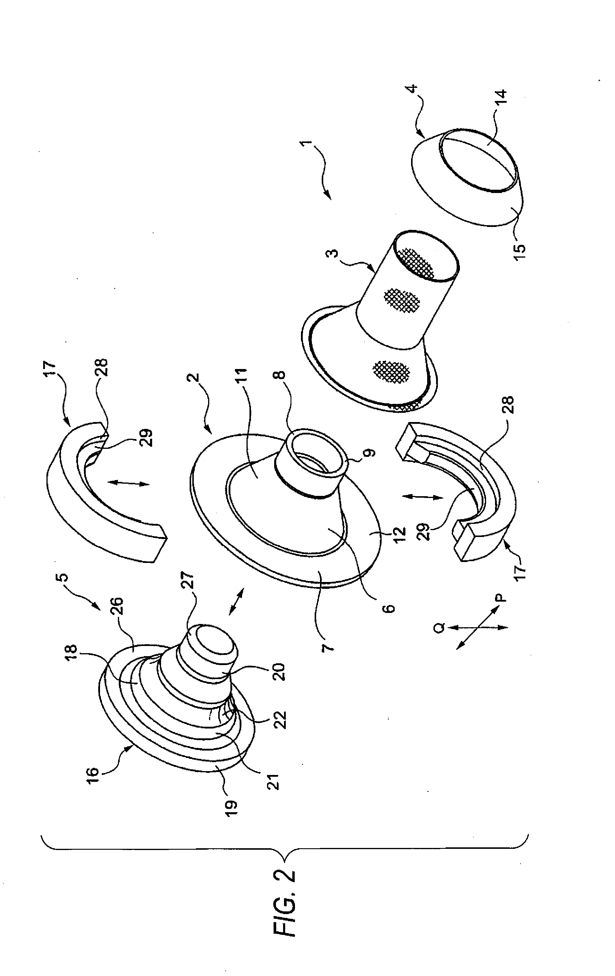
[0031]In FIG. 1, reference number 1 indicates a shield wire for electrically connecting a motor and an inverter, for example, in an electric vehicle or a hybrid car (a part relevant to the present invention is shown solely). The shield wire 1 according to the present embodiment is used as a motor cable, and constructed from: a plurality (e.g., three) of electric wires (not shown); a metal shield shell 2 having electric conductivity; a tube-shaped braid 3 having electric conductivity and collectively covering the plurality of electric wires; and a caulking ring 4 of metal ring construction that is inserted over the end part of the braid 3 and then undergoes caulking.

[0032]The shield wire 1 has an end part structure that the end part of the braid 3 is connected and fixed to the shield shel...

embodiment 2

[0049]A second embodiment is described below with reference to the drawings. FIG. 5 is a sectional view showing a braid fixing structure for shield wire and a caulking die according to the present invention. Here, like members to those in the first embodiment are designated by like numerals, and hence their detailed description is omitted.

[0050]In FIG. 5, the shield wire 41 has a different shape of the end part of the braid 3 from that of the shield wire 1 according to Embodiment 1. The other points in the configuration are the same. The end part shape of the braid 3 is such that the end part is folded inward so that a two-ply structure is formed. The two-ply structure in the end part of the braid 3 increases the density of the mesh of the braid 3 connected and fixed to the braid holding part 6. Thus, even when the end part of the braid 3 is spread and then inserted (outside fit) over the braid holding part 6, the mesh opening is suppressed. This provides an effect that satisfactori...

embodiment 3

[0051]A third embodiment is described below with reference to the drawings. FIG. 6 is a sectional diagram showing a braid fixing structure for shield wire and a caulking die according to the present invention.

[0052]In FIG. 6, a shield wire 51 according to the present embodiment has: a plurality (e.g., three) of electric wires (not shown); a metal shield shell 52 having electric conductivity; a tube-shaped braid 53 having electric conductivity and collectively covering the plurality of electric wires; and a caulking ring 54 of metal ring construction that is inserted over the end part of the braid 53 and then undergoes caulking.

[0053]The shield wire 51 has an end part structure that the end part of the braid 53 is connected and fixed to the shield shell 52 as a result of caulking performed by the caulking die 55. Further, the shield wire 51 has an end part structure that the braid 53 is grounded through the shield shell 52 to a shielding case (not shown). In the connection and fixati...


PUM

PropertyMeasurementUnit
electric conductivityaaaaaaaaaa
sizeaaaaaaaaaa
timeaaaaaaaaaa

Abstract

A step-shaped receptacle part 22 depressed in a step shape in a circumferential direction is provided in a middle part of an outer peripheral surface 21 of a core body 18 of a core 16 constituting a caulking die 5. Further, a part on a core insertion start side relative to the step-shaped receptacle part 22 is formed in a size smaller than that at the position of the step-shaped receptacle part 22. Caulking is performed by the caulking die 5 having this configuration, so that the fixing state viewed in a cross section in a connection and fixation target part is made such that a plurality of bent parts are formed in accordance with the sectional shape of the step-shaped receptacle part 22.

Description

BACKGROUND[0001]1. Field of the Invention[0002]The present invention relates to a braid fixing structure for shield wire and a caulking die used for this fixing structure.[0003]2. Description of the Related Art[0004]A shield wire (corresponding to a motor cable, in this example) like that connected to an inverter or a motor in an electric vehicle or a hybrid car is constructed from: a plurality of electric wires; a metal shield shell having electric conductivity; and a tube-shaped braid having electric conductivity and collectively covering the plurality of electric wires. The shield wire has an end part structure that the braid end part is connected and fixed to the shield shell. Further, the shield wire has an end part structure that the braid is grounded through the shield shell to a shielding case.[0005]As for the connection and fixation between the braid end part and the shield shell, the following Patent Document 1 discloses as follows. That is, as means of connecting and fixi...

Claims


Application Information

Patent Timeline
Patent Type & Authority Applications(United States)
IPC IPC(8): H01R4/18H01R43/042
CPCY10T29/53235B60R16/0222H02G3/22
Inventor ADACHI, HIDEOMIKUBOSHIMA, HIDEHIKO
Owner YAZAKI CORP
Why Eureka
Try Eureka