
Presentation device

a technology of a presentation device and a display screen, which is applied in the direction of instruments, television systems, color signal processing circuits, etc., can solve the problems of inconvenient button operation, poor presentation effect, etc., and achieve the effect of being versatile and effectiv

Inactive Publication Date: 2010-12-02
ELMO CO LTD
View PDF11 Cites 7 Cited by
  • Summary
  • Abstract
  • Description
  • Claims
  • Application Information

AI Technical Summary

Benefits of technology

[0007]An advantage of some aspects of the invention is to provide a presentation device whereby masking display during a presentation can be carried out through a simple operation, without the need for laborious operations.
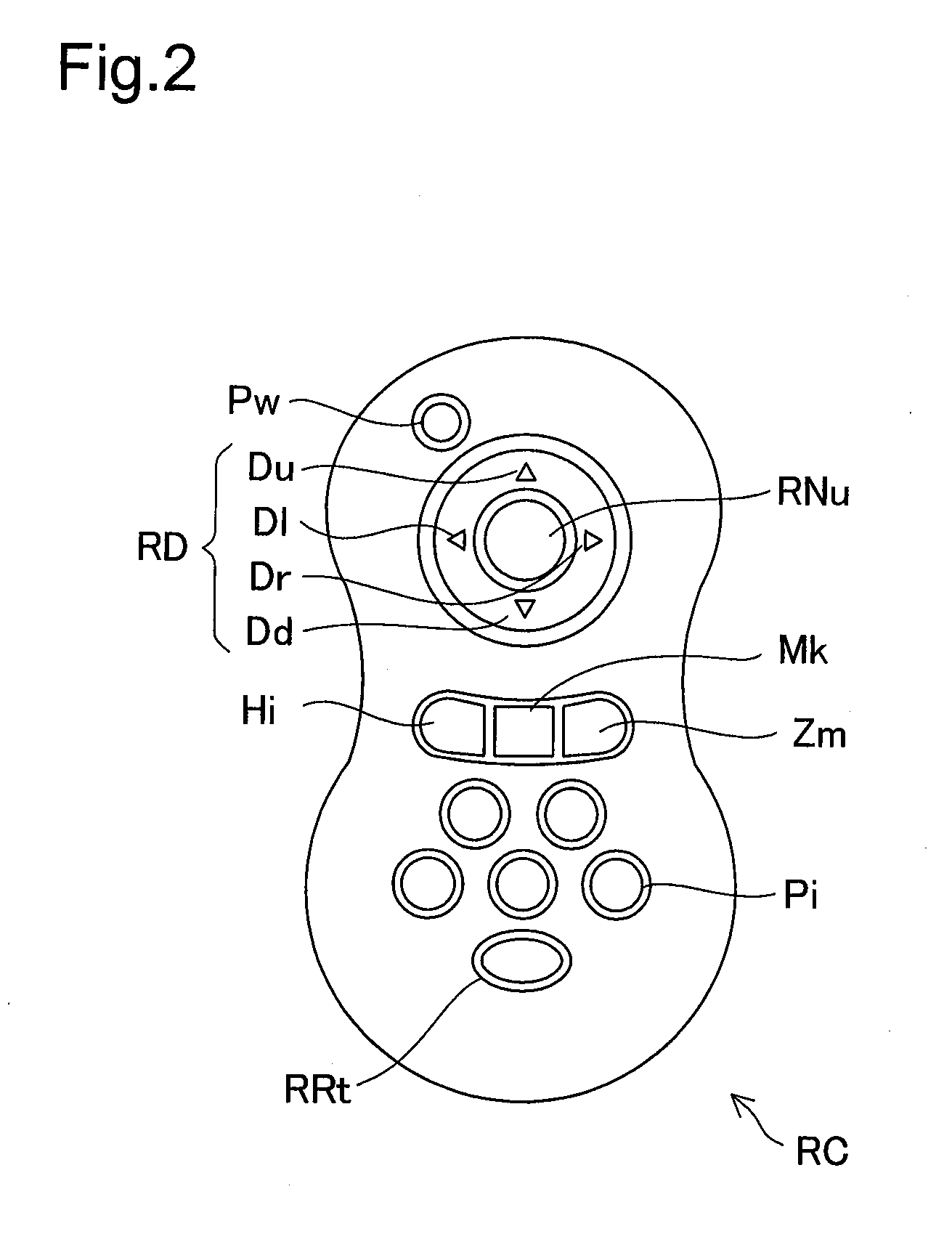
[0009]In the presentation device according to the first aspect, when the video signal controller performs signal processing of the picture signal from the image sensor and outputs a video signal, a video image is displayed on the display unit. In response to a wireless signal that reflects an instruction received from the remote controller, the video signal controller changes the video image that is displayed on the display unit. Specifically, the masking settings means of the video signal controller are used to preset a number of setting values which include masking size and the brightness differential between the masking region and other areas. While the video signal processing unit is producing the live video image within field captured by the image sensor and outputting a video feed to the display unit, if the video signal controller receives from the masking instruction unit of the remote controller RC a wireless signal instructing that a masking region be established, the masking image display controller establishes a masking region in a portion of the live video image, according to the masking region and brightness differential that are set previously by the masking setting portion. Also, if the masking image display controller receives an instruction from the position instruction unit of the remote controller, it changes the location of the masking region. Specifically, from a location away from the document and in proximity to the display unit, through one-touch operation of the remote controller the user may produce an accentuated display in which a portion of the live video image is differentiated from other areas by a brightness differential, and moreover may change the location of the masking region. Consequently, in the course of a presentation, masking display can be carried out through a simple operation, without the need for laborious operations such as setting the masking region.

Problems solved by technology

A resultant problem is that effectiveness of presentation to the audience tends to suffer; and the need to operate buttons etc. is inconvenient as well.

Method used


Image

  • Presentation device
  • Presentation device
  • Presentation device

Examples


Embodiment Construction

(1) General Configuration of Document Presentation System 10

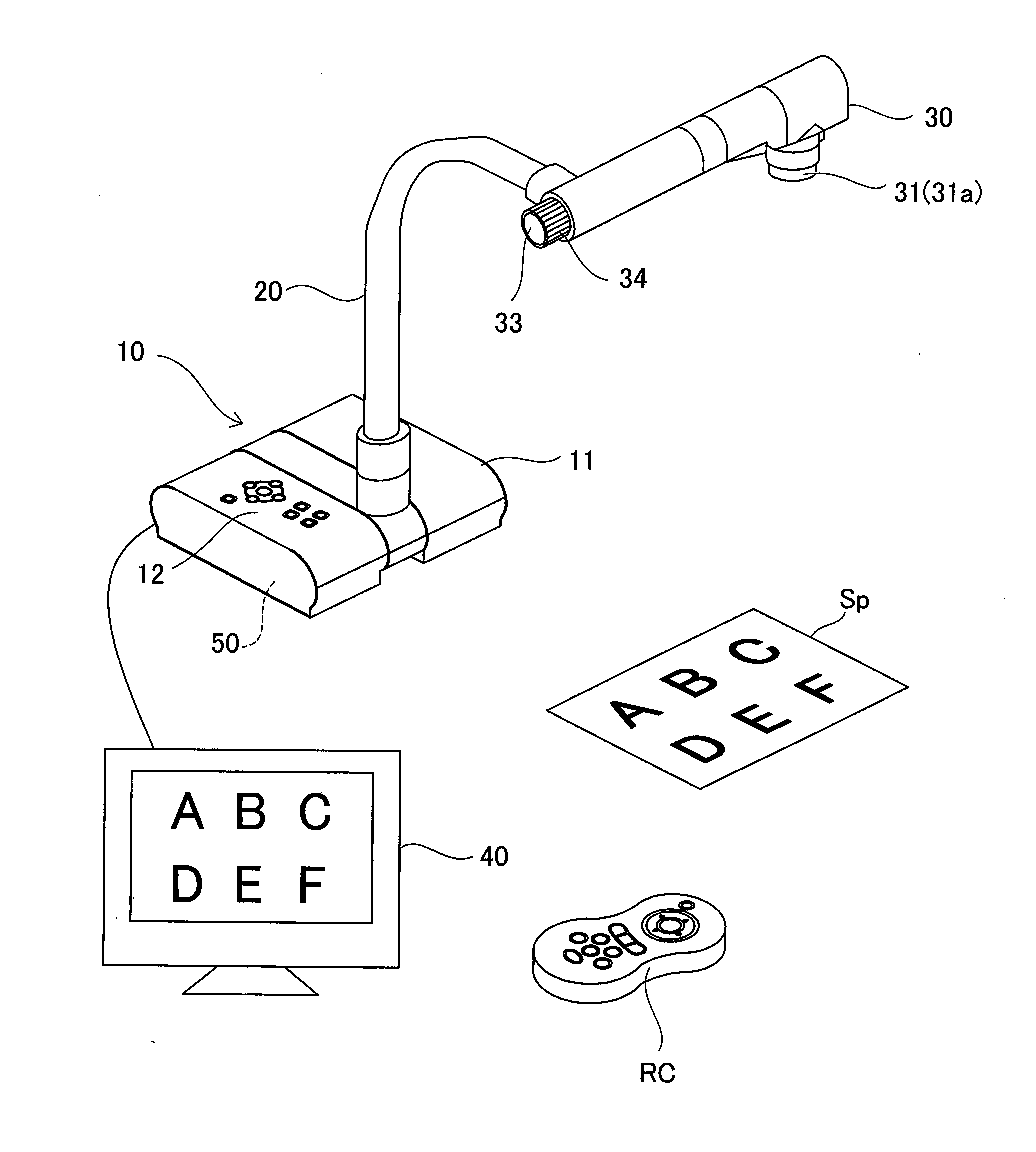
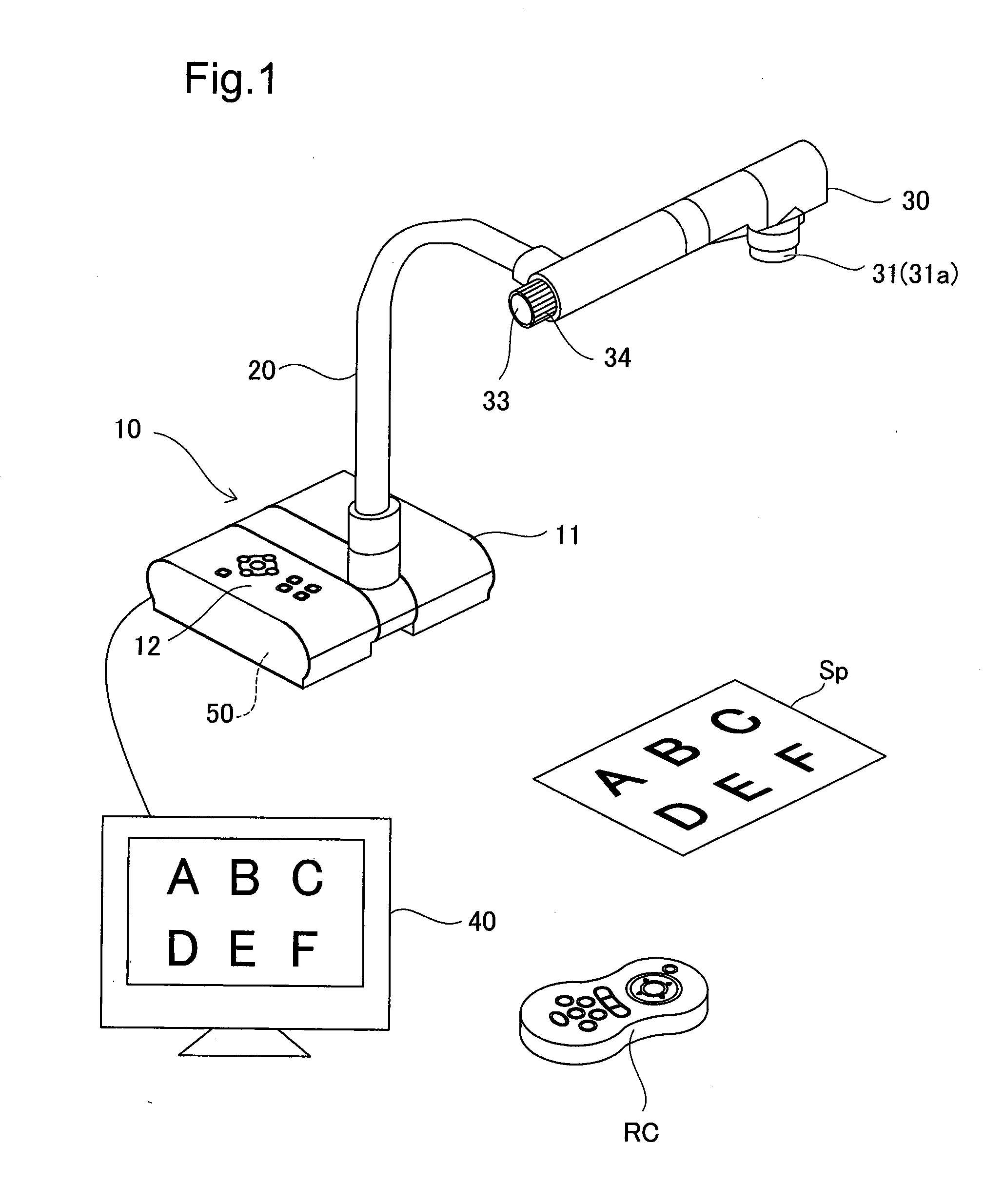
[0027]FIG. 1 is an illustration depicting a general configuration of a document presentation device according to an embodiment of the present invention. The document presentation device 10 is furnished with a control base 11 adapted to be placed on a desk or the like; a support arm 20 that curves upward from the control base 11; a camera head 30 that is secured to the upper end of the support arm 20; and a video signal controller 50 that is housed inside the unit. Also provided is a remote controller RC for controlling the video signal controller 50.

[0028]A control panel 12 is provided on the upper face of the control base 11. The control panel 12 includes a power switch; OSD (On-Screen Display) control buttons, discussed later; various buttons for switching between video outputs; a button for adjusting the brightness of the camera image, and so on. On the back panel of the control base 11 are provided various input / output ...


PUM


Abstract

A document presentation device 10 includes a video signal controller 50 adapted to output a video signal of a video image for display on a display unit 40; and a remote controller RC. The video signal controller 50 includes a video signal processing unit 60 for creating a live video image within the field captured by an image sensor 31a; a masking setting unit for setting the brightness differential of the masking region; and a masking image display control unit that upon receiving an instruction from a masking instruction unit of the remote controller RC, sets a portion of the live video image to a masking region based on settings that are set in advance through the masking settings portion, and displays the live video image on the display unit 40; and that upon receiving an instruction from a position instruction unit of the remote controller RC changes the position of the masking region.

Description

[0001]This application claims the benefit of and priority from Japanese Application No. 2009-126294 filed May 26, 2009, the content of which is incorporated herein by reference.BACKGROUND OF THE INVENTION[0002]1. Field of the Invention[0003]The present invention relates to a presentation device adapted to capture and generate an image from a document etc, with a camera, and to display the image on an external display device.[0004]2. Description of the Related Art[0005]Presentation devices like that disclosed in JP-A 2008-301069 are utilized in instances in which document images captured by a camera are to be displayed on a monitor or projector for the purpose of making a presentation to an audience. Functions required of such document presentation devices include the ability to display documents in various ways so that the document content can be presented simply and effectively to an audience; for example, functions of enlarging or highlighting selected portions of a document in th...

Claims


Application Information

Patent Timeline
IPC IPC(8): H04N5/14H04N5/232
CPCH04N1/3875H04N5/232H04N5/23296G09B5/06H04N7/183H04N23/63H04N23/69H04N1/387H04N5/74H04N23/00
Inventor TANABE, MASAKIFUTAMURA, SHINYAFURUYA, MASATAKA
Owner ELMO CO LTD
Learn More