Cooling Device For A Circuit Breaker And Circuit Breaker Comprising Such Device

a circuit breaker and cooling device technology, applied in the direction of heat/cooling contact switches, electrical apparatus construction details, contacts, etc., can solve the problems of limiting the power that can be drawn by the device, and affecting the cooling effect of the circuit breaker. achieve the effect of improving the cooling effect of the circuit breaker

Active Publication Date: 2010-12-02
ABB SPA
View PDF4 Cites 24 Cited by
  • Summary
  • Abstract
  • Description
  • Claims
  • Application Information

AI Technical Summary

Benefits of technology

[0017]Therefore, the present invention is directed toward addressing the aforementioned problems and providing a solution that makes i...

Problems solved by technology

Of these three installation configurations, the first one is the simplest and least expensive, but it is only suitable for solutions that are definitive and in any case non-flexible; on the other hand, the configurations of the removable and withdrawable type offer a greater flexibility.
Installations of circuit breakers of the removable and withdrawable type do have at least one drawback compared to the fixed-type installation.
In practice, the most critical energy dispersion peaks due to the Joule effect, with consequent undesirable heat production, tend to occur in t...

Method used


Image

  • Cooling Device For A Circuit Breaker And Circuit Breaker Comprising Such Device
  • Cooling Device For A Circuit Breaker And Circuit Breaker Comprising Such Device
  • Cooling Device For A Circuit Breaker And Circuit Breaker Comprising Such Device

Examples


Embodiment Construction

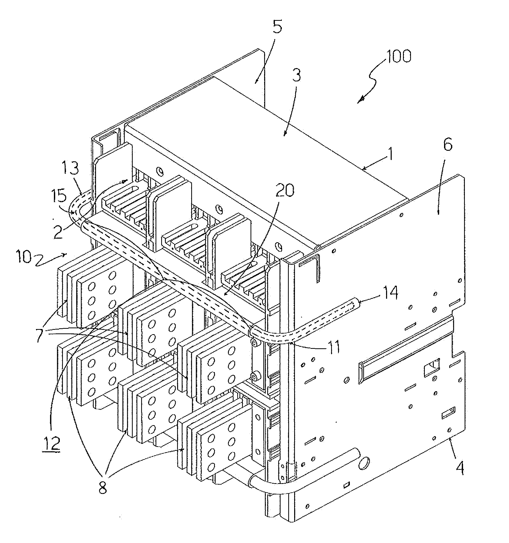
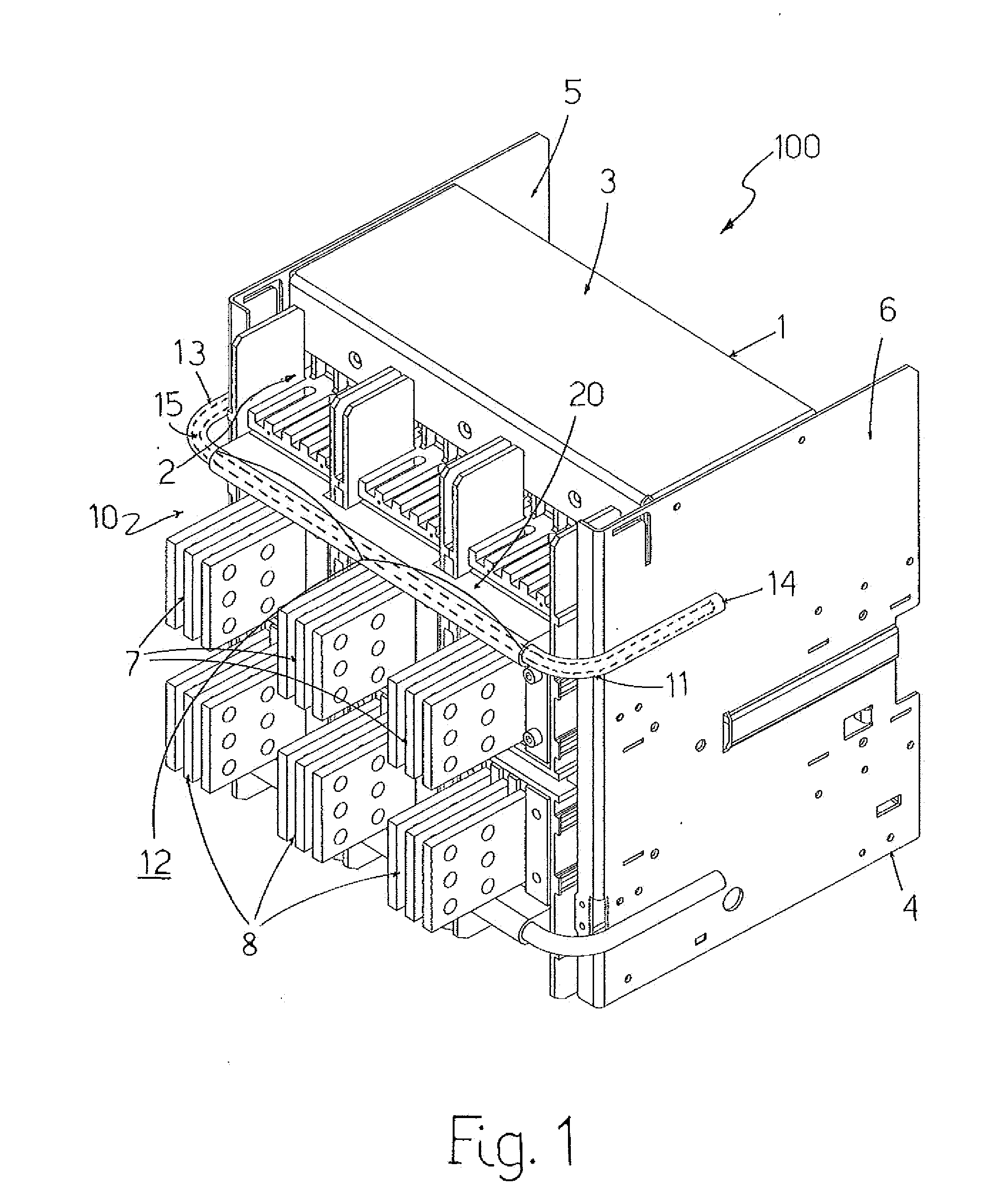
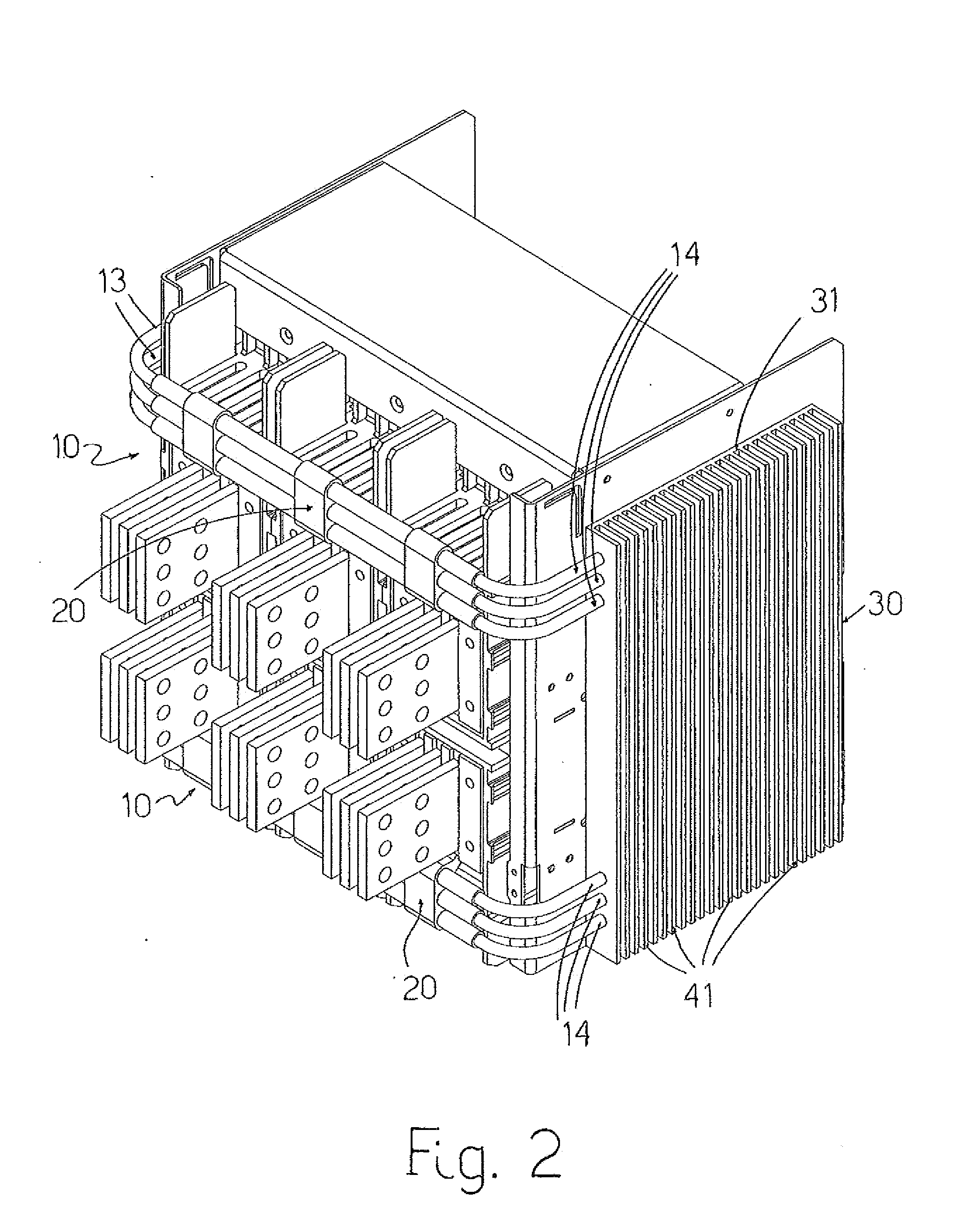
[0024]In FIGS. 1-4 there is illustrated a circuit breaker 100, for example, a low-voltage one, viewed from the rear, which comprises a case constituted by a single piece or in multiple elements assembled together, having a front wall 1, a rear wall 2, an upper wall 3, a lower wall 4, and two flanks 5 and 6.

[0025]According to embodiments which are well known in the art and, therefore, not described here in detail, inside the case the breaking part of the circuit breaker is housed, which usually comprises, for each pole or phase of the electrical circuit, inside which the circuit breaker is inserted, an arc chamber inside which a pair of electrical contacts are positioned that couple to / separate from each other; moreover, the circuit breaker 100 can be realized in a fixed execution, that is, in a single body, or in a withdrawal or removable (plug-in) execution, wherein the part (of the type illustrated in the figures) containing the breaking components is couplable to an adapter in a ...


PUM


Abstract

A cooling device for a circuit breaker which comprises a case having a front wall, a rear wall, an upper wall, a lower wall, two flanks, and a first series of side-by-side terminals and a second series of side-by-side terminals that protrude outside from the case for the connection of the circuit breaker with an electrical circuit. The cooling device includes at least one first body made of a thermal conducting material and which has a central portion suitable for being positioned transversally along and facing the first series of terminals so as to absorb heat generated at the first series of terminals, and a first end portion and a second end portion that protrude from the central portion and are configured so as to receive the heat absorbed by the central portion and to diffuse it outside the cooling device itself.

Description

CROSS-REFERENCE TO RELATED APPLICATION[0001]This application claims priority under 35 U.S.C. §119(a)-(d) to Italian Patent Application Number BG2009A000032, filed on May 28, 2009, the entire contents of which are hereby incorporated by reference.BACKGROUND OF THE INVENTION[0002]The present invention relates to a cooling device for a circuit breaker and to a circuit breaker which comprises such cooling device as well as to a switchboard which comprises such circuit breaker.[0003]As known, low-voltage breaking devices (that is for applications with nominal voltages up to 1000V AC / 1500V DC), such as automatic circuit breakers, disconnectors, and contactors, commonly referred to as “switching devices” and hereinafter collectively referred to as circuit breakers, are devices designed for allowing correct operation of specific parts of electrical systems and installed loads.[0004]Such devices are usually installed inside distribution switchboards located in electrical systems. Distributio...

Claims


Application Information

Patent Timeline
IPC IPC(8): H02B1/56H05K7/20
CPCH01H9/52H01H2009/523H02B1/56H02B11/04
Inventor BORTOLI, MARIOBERGAMINI, ALESSIOAGOSTINI, BRUNOAGOSTINI, FRANCESCOCHARTOUNI, DANIELBUEHLER, TILO
Owner ABB SPA
Why Eureka
Try Eureka