Rotor and x-ray ct scanners

a ct scanner and rotor technology, applied in tomography, medical science, diagnostics, etc., can solve the problems of mechanical stacking error, image artifacts, and increased cost, and achieve the effect of reducing mechanical stacking error

Active Publication Date: 2010-12-02
KONINKLIJKE PHILIPS ELECTRONICS NV
View PDF9 Cites 4 Cited by
  • Summary
  • Abstract
  • Description
  • Claims
  • Application Information

AI Technical Summary

Benefits of technology

[0007]An object of the invention is to reduce relative motion between the focal spot of a radiation source and detector modules so as to reduce imaging artifacts. This invention achieves the object by providing a rotor, which integrates the radiation source and detector modules into a circular body, the rotor comprising:
[0011]By mounting the radiation source into the cavity with shielding on the circular body, the conventional housing for radiation source and shield are removed, resulting in reduction of focal spot motion caused by motion of the structure onto which the radiation resource is mounted in conventional CT scanners.
[0013]By directly mounting the detector modules on the circular body, the centrifugal force on the detection modules is transmitted directly to the circular body instead of through an intermediate structural housing, resulting in reduction of the detector modules motion relative to the focal spot. This also helps mitigate mechanical stack-up error caused by the intermediate structural housing.
[0014]In an embodiment, the detection modules are situated on a circle arc-shaped surface. The center of the circle arc-shaped surface is at the rotation center of the rotor, and the detector modules point towards the focal spot of the X-rays radiation. Compared to the conventional arrangement, in which the detection modules are situated on a circle arc centered at the focal spot of the X-rays radiation, this arrangement reduces the thinning of the circular body near the first and last detector module and thus may makes the circular body more substantial.
[0015]In an embodiment, the detector modules engage into respective saw-shaped grooves on the circle arc-shaped surface. The arrangement improves alignment of the detector modules with the focal spot.

Problems solved by technology

One way to combat the force is to make the cradle structure more substantial, but that may increase cost and cause the cradle to be heavy.
The large centrifugal forces on the cradle will cause detectors motion, which may results in image artifacts.
For some CT scanner, the x-ray tube shelf has been known to move under centrifugal force resulting in an undesirable motion of the focal spot, which introduces image artifacts.

Method used


Image

  • Rotor and x-ray ct scanners
  • Rotor and x-ray ct scanners
  • Rotor and x-ray ct scanners

Examples


Embodiment Construction

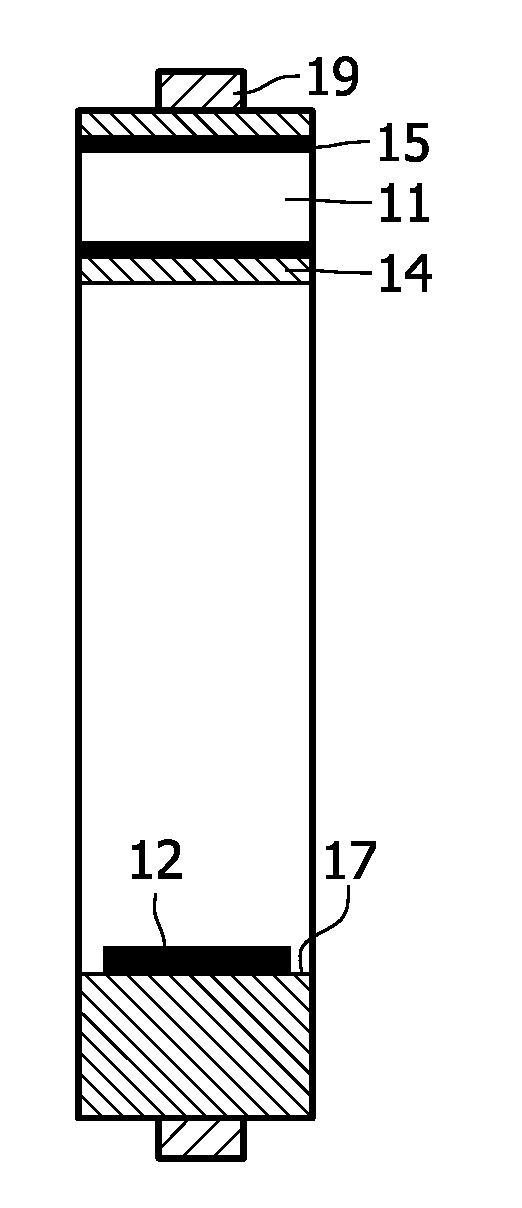
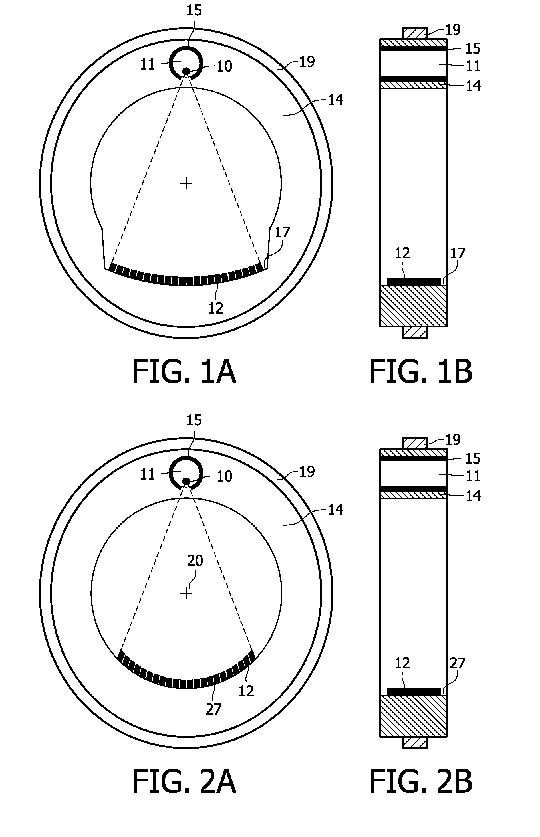
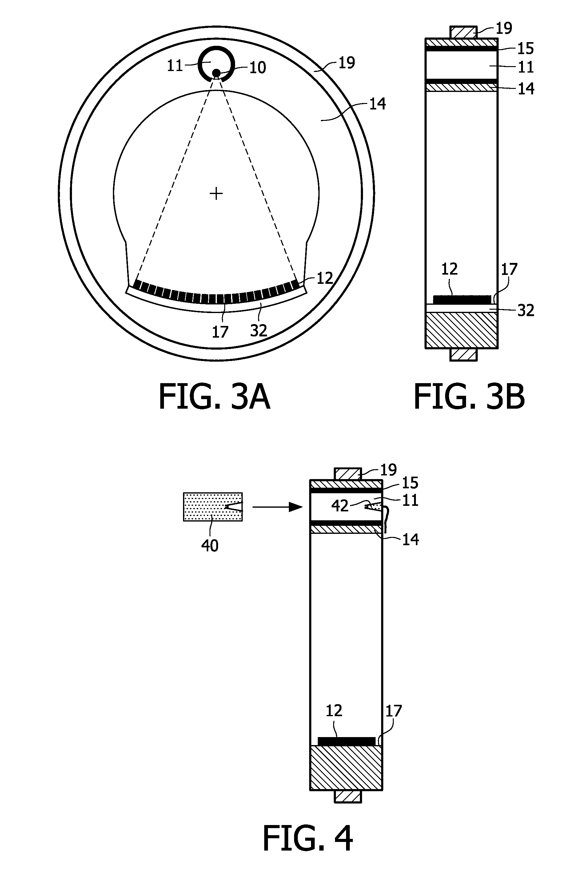
[0026]FIGS. 1A and 1B are schematic sectional views illustrating an embodiment of a rotor in accordance with the invention. The rotor comprises:[0027]a radiation source having a focal spot 10 for radiating beam towards a subject;[0028]detection means 12 for generating signals responsive to energy attenuation of said beam;[0029]a circular body 14 having a cavity 11 for housing the radiation source, and a circle arc-shaped surface 17, 27 on which the detection means 12 are mounted;

wherein the circle arc-shaped surface 17, 27 is placed opposite to the cavity 11 with respect to the subject, said cavity 11 comprising an inside surface mounted with a shield 15 for shielding the radiation not towards the subject.

[0030]Optionally, the rotor comprise bearing 19, which connects the circular body 14 to a stator, which may be fixed in a gantry, and thus enables the rotor to rotate around the subject with support of the stator. The bearing 19 can be on the outside of the rotor or inside of the r...


PUM


Abstract

The invention relates to a rotor comprising a radiation source having a focal spot for radiating beam towards a subject, detection means for generating signals responsive to energy attenuation of said beam and a circular body having a cavity for housing the radiation source, and a circle arc-shaped surface on which the detection means are mounted. The circle arc-shaped surface is placed opposite to the cavity with respect to the subject, said cavity comprising an inside surface mounted with a shield for shielding the radiation not towards the subject. In this way, the conventional housing for radiation source and shielding are removed, resulting in reduction of focal spot motion caused by motion of the conventional housing. Furthermore, this invention proposes to mount the detection means directly on the circular body without an intermediate structural housing that reduces the detector modules motion relative to the focal spot.

Description

FIELD OF THE INVENTION[0001]The invention relates to computerized tomography (CT) X-ray imaging and in particular, relates to a rotor and X-ray CT scanners for X-ray CT imaging.BACKGROUND OF THE INVENTION[0002]In CT X-ray imaging of a patient, X-rays are used to image internal structure and features of a region of the patient body. The imaging is performed by a CT-imaging system, hereinafter referred to as a “CT scanner”, which generally comprises an X-ray source and an array of closely spaced X-ray detectors positioned to face the X-ray source. The X-ray source and array of detectors are mounted in a gantry so that a person being imaged with the CT scanners, generally lying on an appropriate support couch, can be positioned within the gantry between the X-ray source and the array of detectors. The gantry and couch are moveable relative to each other so that the X-ray source and detector array can be positioned axially, along a “z-axis”, at desired location along the patient's body....

Claims


Application Information

Patent Timeline
Patent Type & Authority Applications(United States)
IPC IPC(8): H05G1/02
CPCA61B6/035A61B6/56A61B6/4291
Inventor LUHTA, RANDALL PETERSHARPLESS, RONALDMILLER, LESTER
Owner KONINKLIJKE PHILIPS ELECTRONICS NV
Why Eureka
Try Eureka