Hydraulic end float adjuster

Active Publication Date: 2010-12-02
WAUKESHA BEARINGS CORP
View PDF15 Cites 4 Cited by
  • Summary
  • Abstract
  • Description
  • Claims
  • Application Information

AI Technical Summary

Benefits of technology

[0006]The invention provides systems and methods for reducin

Problems solved by technology

The size of the clearance can affect the performance of a system.
Specifically, a

Method used


Image

  • Hydraulic end float adjuster
  • Hydraulic end float adjuster
  • Hydraulic end float adjuster

Examples


Embodiment Construction

[0033]Although the disclosure hereof is detailed and exact to enable those skilled in the art to practice the invention, the physical embodiments herein disclosed merely exemplify the invention which may be embodied in other specific structures. While the preferred embodiment has been described, the details may be changed without departing from the invention, which is defined by the claims.

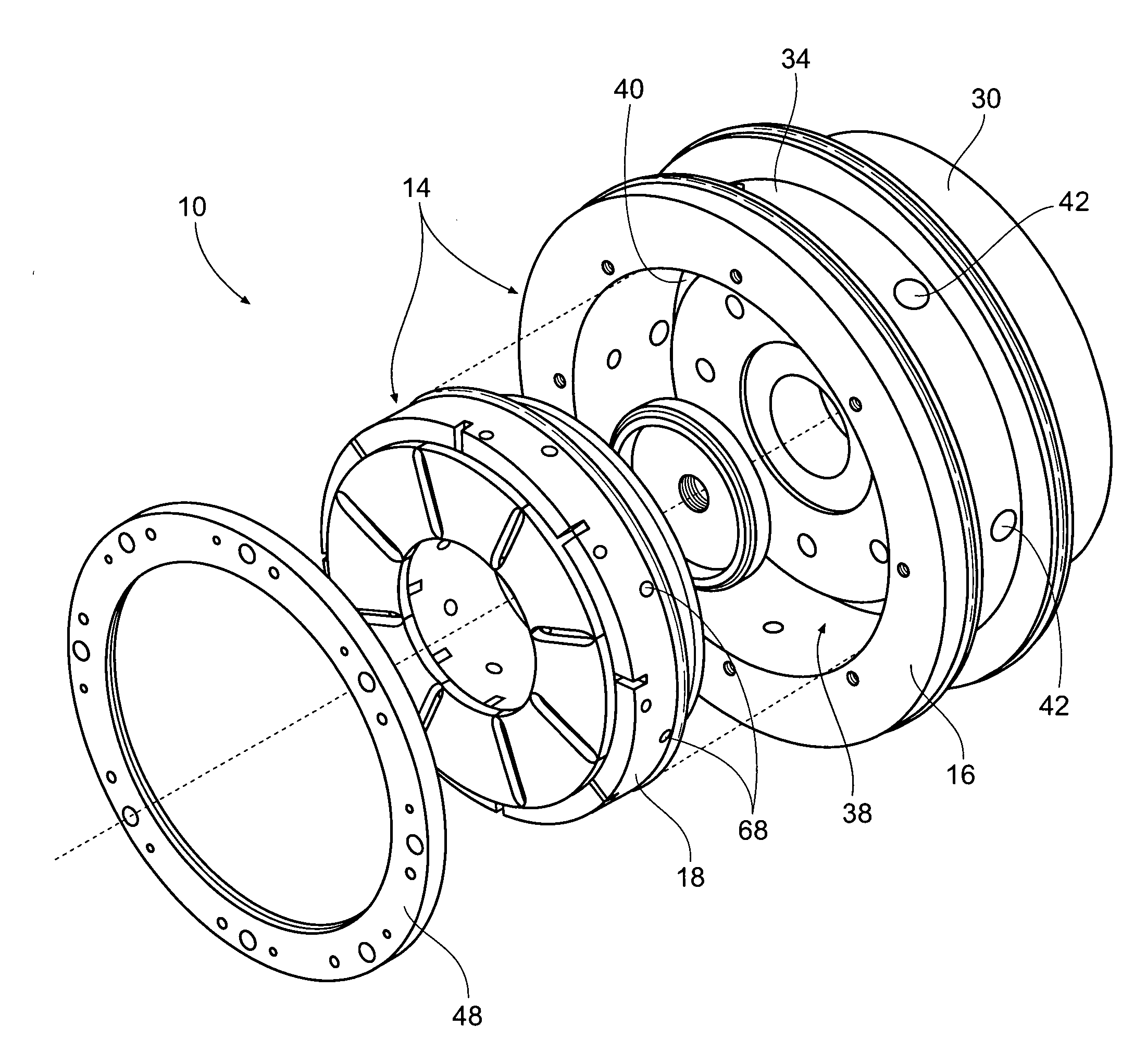
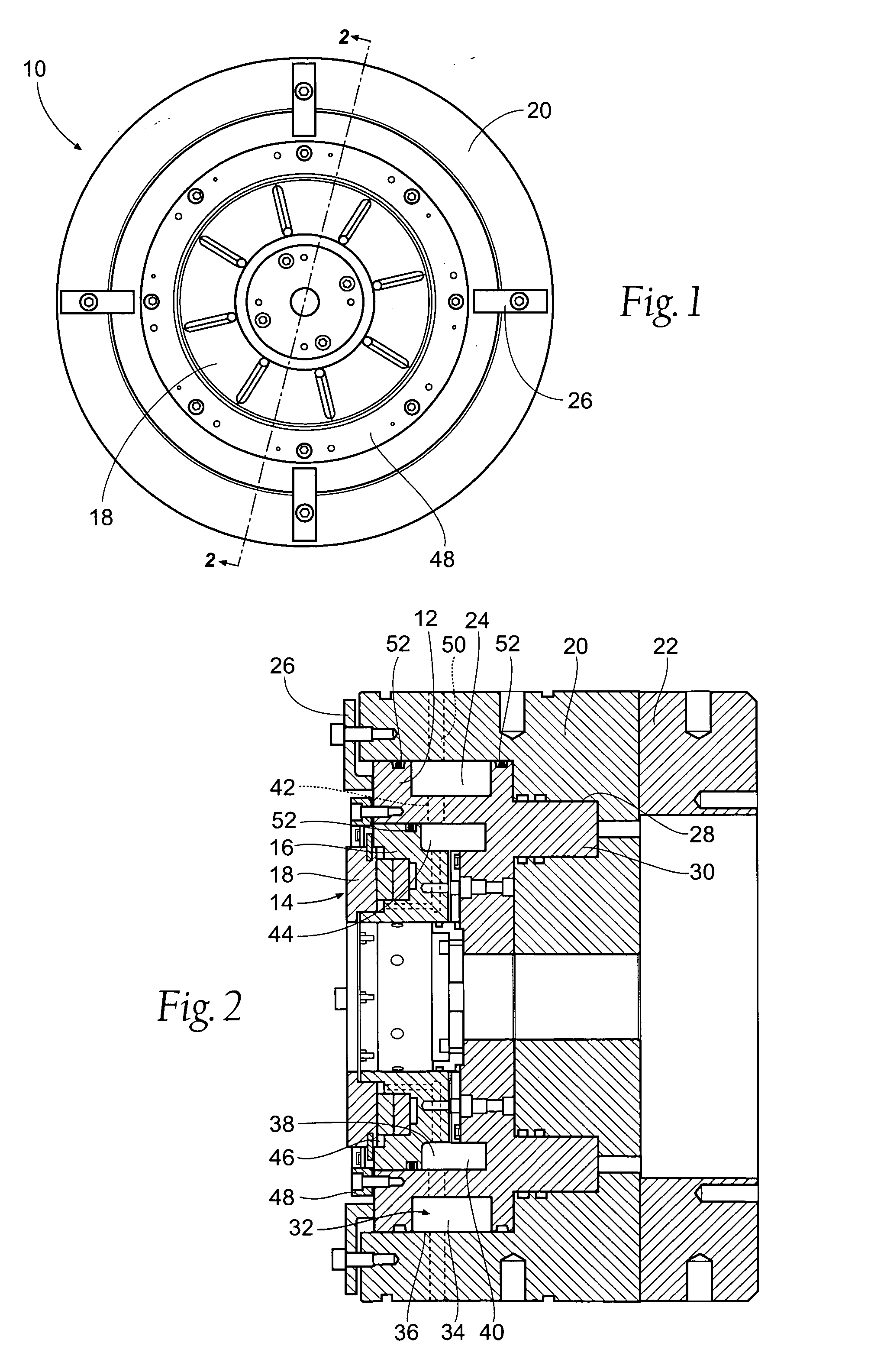
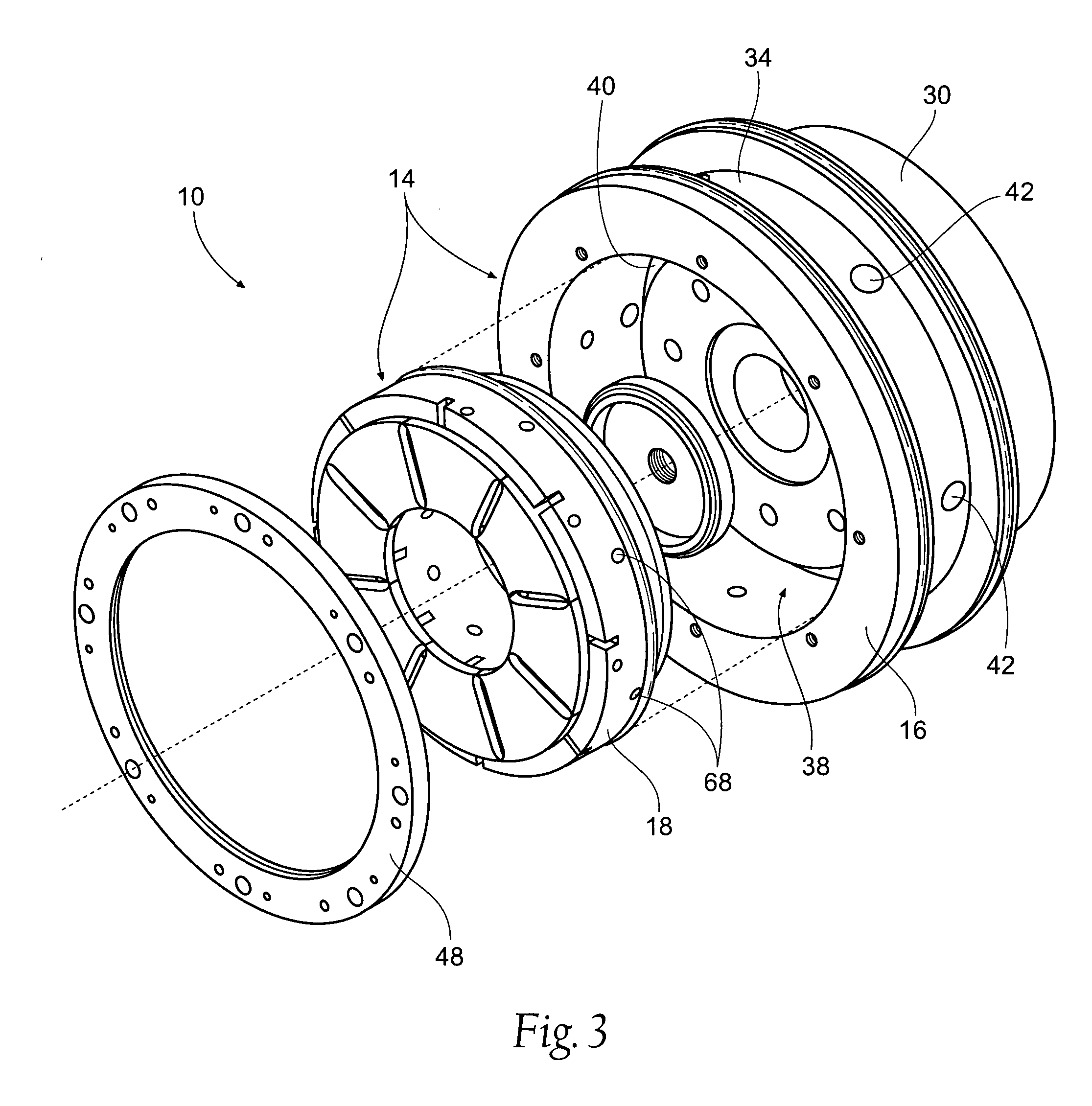
[0034]The illustrated embodiments bearing systems 10,110,210,310 shown in FIGS. 1 through 10 each comprise a bearing housing 12,112,212,312 and a bearing 14,114,214,314. The bearing 14,114,214,314 is preferably a thrust bearing and may be of any type known in the art including, but not limited to a flat thrust face, a taper land thrust bearing or a tilt pad thrust bearing. The bearing 14,114,214,314 is preferably retained at least partially within the bearing housing 12,112,212,312. Preferably at least one fluid cavity 44,144,244,344 is formed between the bearing 14,114,214,314 and the bearing hou...


PUM


Abstract

A bearing system for reducing end clearance and axial vibrations includes a bearing housing and a bearing. The bearing is a thrust bearing and may be of any type, such as a flat thrust face, a taper land thrust bearing or a tilt pad thrust bearing. The bearing housing includes a cavity to hold the bearing. A fluid cavity is formed between the bearing and the bearing housing. At least one fluid passageway extends through the bearing housing to feed fluid to the fluid cavity. As fluid is introduced to the fluid cavity the pressure in the cavity moves the bearing outward, away from the bearing housing and towards the rotating thrust collar, reducing the clearance, or space, between the face of the bearing and the thrust collar, reducing or eliminating the vibrations.

Description

BACKGROUND OF THE INVENTION[0001]A thrust bearing is a type of bearing which allows for rotation between parts while supporting an axial load. Fluid film bearings are a type of thrust bearing wherein the bearing's loads are supported on a thin fluid layer or film of liquid or gas which is formed between the bearing surfaces in relative motion. Fluid bearings are often used in many applications covering a wide range of loads and speeds.[0002]Flat land thrust bearings, taper thrust bearings (with or without a land), and tilt pad thrust bearings are three types of fluid film thrust bearings. A flat land thrust bearing utilizes a flat plate or washer, often with radial grooves, to carry the axial load. Taper land thrust bearings utilize plates similar to a flat land thrust bearing but with multiple profiles (taper lands, as one example) machined into the bearing surface. Tilt pad thrust bearings utilize a number of individual segments (or pads), each of which is configured to pivot or t...

Claims


Application Information

Patent Timeline
IPC IPC(8): F16C27/08
CPCF16C17/04F16C17/06F16C25/02
Inventor BLAIR, BARRY J.PITSCH, DONALD S.
Owner WAUKESHA BEARINGS CORP
Why Eureka
Try Eureka