Water-Cooled Oil-Free Air Compressor

Inactive Publication Date: 2010-12-02
HITACHI IND EQUIP SYST CO LTD
View PDF8 Cites 38 Cited by
  • Summary
  • Abstract
  • Description
  • Claims
  • Application Information

AI Technical Summary

Benefits of technology

[0028]According to the present invention, coolers can be simplified and it is possible to provide a water-cooled t

Problems solved by technology

In such a compressor, the space occupied by the coolers and cooler inlet and outlet pipes in the compressor package must be large, which is an impediment to compressor size reduction.
This means that the cooler volume must be large and it is difficult to reduce the overall compressor size.
Furthermore, since the intercooler and aftercooler lie in the compressed air discharge route, there is high pressure air in the air paths inside the coolers.
A large compressor which deals with a large volume of air has a pr

Method used


Image

  • Water-Cooled Oil-Free Air Compressor
  • Water-Cooled Oil-Free Air Compressor
  • Water-Cooled Oil-Free Air Compressor

Examples


first embodiment

[0048]The first embodiment of the present invention will be described in detail referring to the accompanying drawings. The description will be given below by taking as an example a screw compressor which compresses air by rotation of male and female rotors.

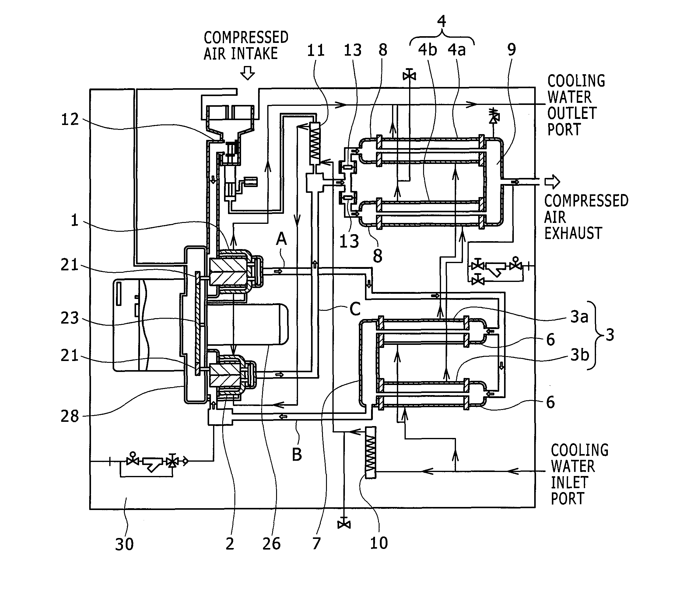
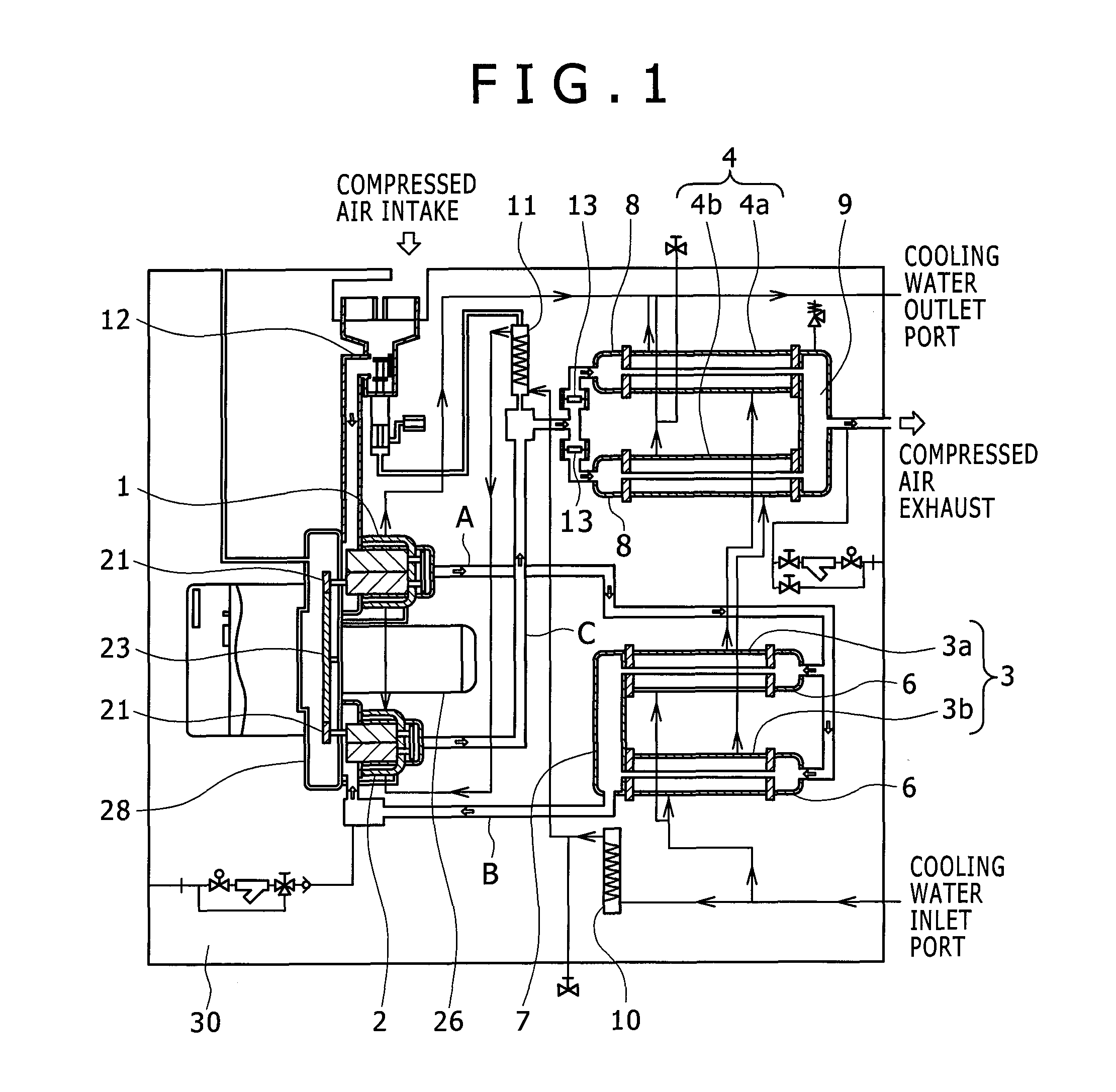
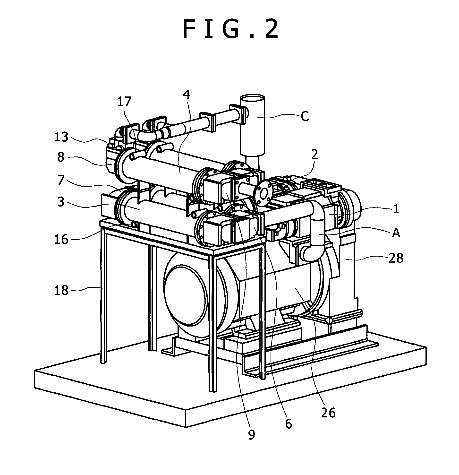
[0049]FIG. 1 is a schematic diagram showing a water-cooled two-stage oil-free screw compressor 30 having a low pressure stage compressor body 1 and a high pressure stage compressor body 2. The low pressure stage compressor body 1 and high pressure stage compressor body 2 each include a pair of rotors, i.e. a male rotor and a female rotor. The compressor according to this embodiment is a screw air compressor which compresses air by rotation of the male and female rotors.

[0050]Pinion gears 21 are fitted to the axial ends of the male rotors of the low pressure stage compressor body 1 and high pressure stage compressor body 2. These pinion gears 21 are engaged with a bull gear 23 fitted to one end of a driving shaft inside a gear cas...


PUM


Abstract

A water-cooled oil-free air compressor which features compactness and ensures improved productivity and maintainability. The compressor is an oil-free screw compressor which includes a low pressure stage compressor body, an intercooler for water-cooling the compressed air discharged from the low pressure stage compressor body, a high pressure stage compressor body for further compressing the compressed air cooled by the intercooler, and an aftercooler for water-cooling the air discharged from the high pressure stage compressor body. The intercooler and aftercooler each have a plurality of units, all of which are almost equal in shape. A cooler header on each or either of the inlet and outlet sides for compressed air is shared by the units of each cooler.

Description

BACKGROUND OF THE INVENTION[0001]The present invention relates to water-cooled oil-free air compressors and more particularly to air compressors which use a cooling device for cooling the air compressed in multiple stages.[0002]Most conventional two-stage oil-free screw compressors which have a low pressure stage compressor body and a high pressure stage compressor body use an intercooler for cooling the air compressed by the low pressure stage compressor body and an aftercooler for cooling the air compressed by the high pressure stage compressor body.[0003]The compressors as described in JP-A No. H8-61271 and JP-A No. H11-22688 are known as water-cooled two-stage compressors having an intercooler and an aftercooler. In the compressor as described in JP-A No. H8-61271, cooling water is first to the aftercooler and then to the intercooler, and in the compressor as described in JP-A No. H11-22688, the cooling water path is branched into a cooling water path for cooling the intercooler...

Claims


Application Information

Patent Timeline
IPC IPC(8): F04C29/04F04C23/00
CPCF01C21/007F04B39/064F04C18/16F04C23/001F04C28/02F04C29/04F04C2240/70
Inventor ITO, YUJISUZUKI, TOMOOOHTA, HIROSHI
Owner HITACHI IND EQUIP SYST CO LTD
Why Eureka
Try Eureka