
Battery

Active Publication Date: 2010-12-02
SAMSUNG SDI CO LTD
View PDF6 Cites 12 Cited by
  • Summary
  • Abstract
  • Description
  • Claims
  • Application Information

AI Technical Summary

Benefits of technology

[0009]Provision is preferably made for each electrode to be manufactured integrally with its connecting line, thus resulting in great cost advantages for mass production.
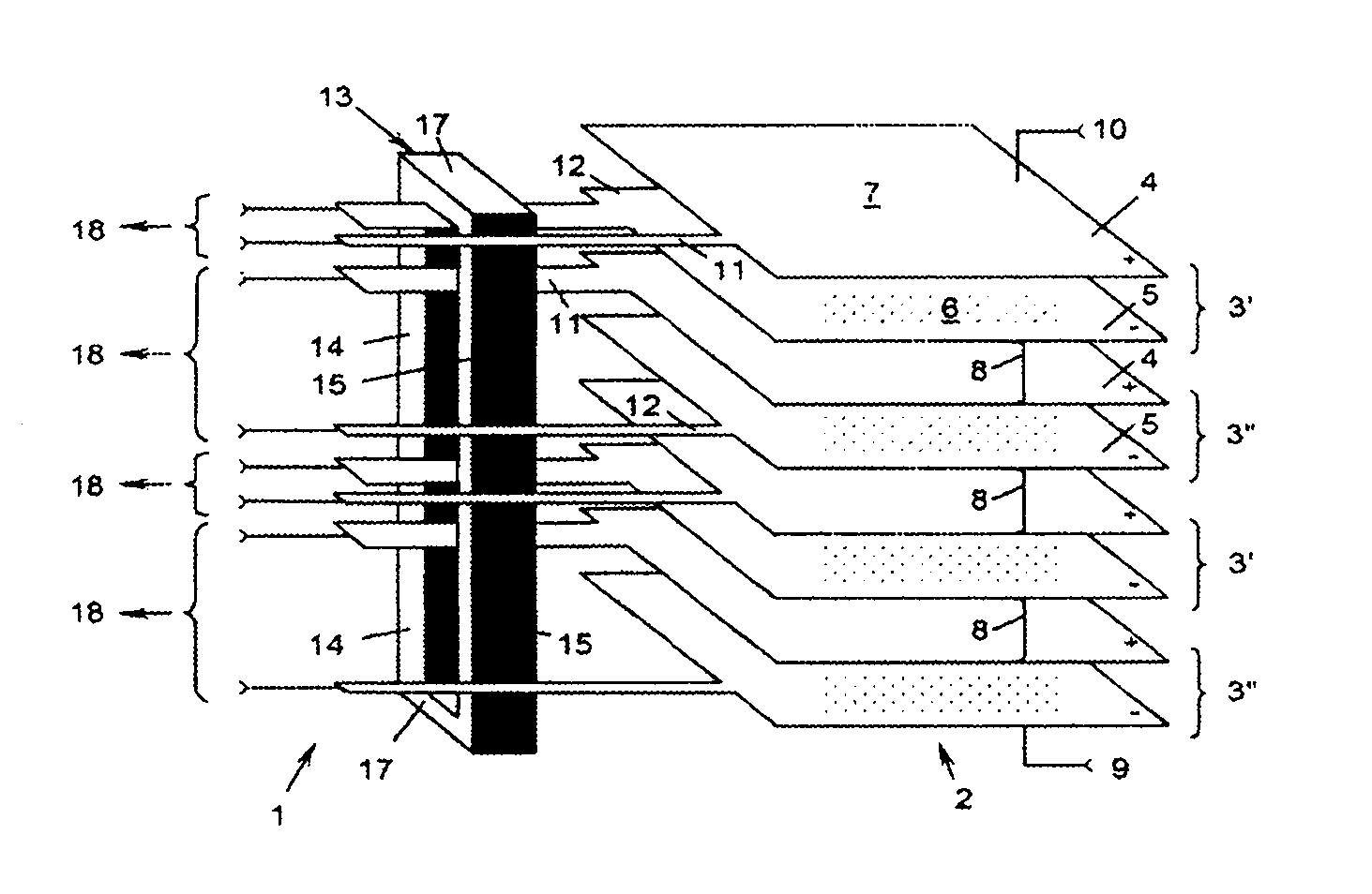
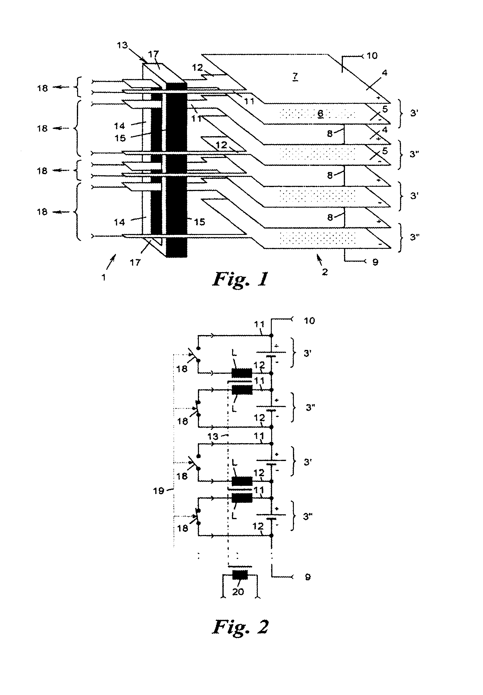
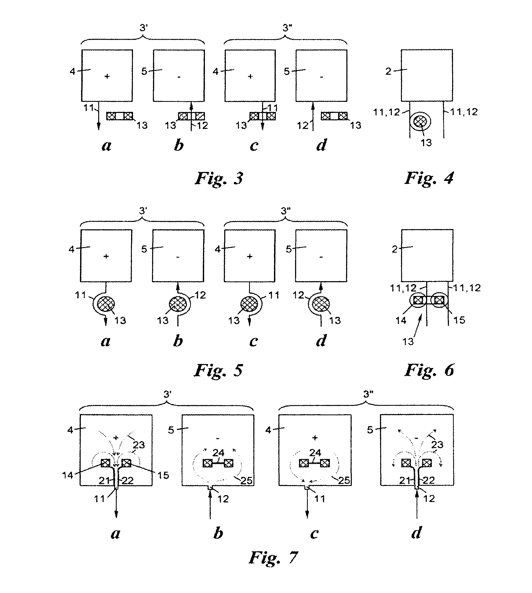
[0012]A further advantageous embodiment of the invention is distinguished in that the core is a U-core or O-core, whose longitudinal limbs pass through the stack, wherein said first set of connecting lines of the cells, bounded by slots from their electrode, pass through between the longitudinal limbs, while in contrast the respective other electrodes of the cells have a separating slot between the longitudinal limbs. This embodiment achieves an optimum of compactness and efficiency: the core is integrated directly in the stack, and the connecting lines are machined directly out of the electrodes, thus minimizing the material requirement. In this way, the connecting lines for carrying current are easily produced equally in the desired sense at right angles to the core extent by production of slots in the electrodes, that is to say the connecting lines act as half-turns or partial turns around the core and are inductively coupled via the core, without requiring any special wiring.
[0014]In this case, it can preferably be provided that the respective other connecting lines of the cells, bounded by slots from their electrode, pass through between the longitudinal limbs in an opposite meandering shape; alternatively, the respective other electrodes of the cells have a separating slot between the longitudinal limbs. In both cases, this easily results in said opposite coupling of the two groups of cells, with even greater coupling being achieved in the first case.
[0015]The cells in the first group and those in the second group preferably alternate with one another, thus further simplifying the design and optimizing the charge balancing by the subdivision of the cells into two groups of equal size.
[0016]It is particularly advantageous if the mutually adjacent electrodes of two adjacent cells are combined to form a common so-called “bipolar” electrode, which is known per se, thus making it possible to save further material.

Problems solved by technology

Provision is preferably made for each electrode to be manufactured integrally with its connecting line, thus resulting in great cost advantages for mass production.

Method used


Image

  • Battery
  • Battery
  • Battery

Examples


Embodiment Construction

[0028]FIG. 1 shows a rechargeable battery 1 which has a stack 2 of (in this case) four cells 3′, 3″ located one above the other. Each cell 3′, 3″ comprises a flat positive electrode 4 and a flat negative electrode 5, as well as a chemical structure or electrolyte 6 located between them.

[0029]The cells 3′, 3″ may be of any type known from technology, for example lithium-ion cells, lithium-polymer cells etc. The precise internal design of the cells 3′, 3″ is not the subject matter of the invention, and will therefore not be explained in any more detail; for the purposes of the present invention, it is sufficient to mention that the cells 3′, 3″ are flat, that is to say they have a relatively large lateral and longitudinal extent on their plane 7 in comparison to the thickness of their electrodes 4, 5 and their electrolyte 6. By way of example, thin vapor-deposited carrier films are used for the electrodes 4, 5 in modern lithium-ion cells with metallic layers, as a result of which the ...


PUM


Abstract

A battery (1) having at least two serially connected cells (3′, 3″) located one above the other in a stack (2) and having flat electrodes (4, 5), the ends of the stack (2) forming the poles (9, 10) of the battery and the electrodes (4, 5) comprising connecting wires (11, 12) protruding sideways from the stack (2), at least one of the connecting wires (11, 12) of all cells (3′, 3″) being inductively coupled via a common core (13) extending approximately in the longitudinal axis of the stack, and the connecting wires (11, 12) of a first group of cells (3′) being coupled in an inductively opposite fashion to the connecting wires (11, 12) of a second group of cells (3″).

Description

BACKGROUND OF THE INVENTION[0001]The present invention relates to a rechargeable battery having at least two series-connected cells which are located one above the other in a stack and have flat electrodes, wherein the ends of the stack form the poles of the rechargeable battery, and the electrodes have connecting lines which emerge from the stack at the side.[0002]Recently, rechargeable batteries such as these have also been used in electrical drive systems for motor vehicles, in order to form high rechargeable-battery pole voltages of more than 100 V by stacking and series connection of an appropriately large number of flat cells.[0003]However, the series connection of the cells has the disadvantage that all the cells are charged with the same charging current, and therefore even minor quality differences between the individual cells lead to different states of charge. Numerous circuits for charge balancing between the individual cells have therefore already been proposed, which a...

Claims


Application Information

Patent Timeline
IPC IPC(8): H01M6/12H02J7/00H01M50/541
CPCY02T10/7055H02J7/0016Y02T10/70
Inventor KRAMMER, GERT
Owner SAMSUNG SDI CO LTD
Learn More