Energy transfer arrangement and method

Active Publication Date: 2010-12-09
POWERMAT TECHNOLOGIES
View PDF12 Cites 28 Cited by
  • Summary
  • Abstract
  • Description
  • Claims
  • Application Information

AI Technical Summary

Benefits of technology

[0006]It is an object of the invention to provide a method and equipment implementing the method in such a way that the above problems are solved. The object of the invention

Problems solved by technology

Conventional use of charging units and wall sockets often involves a number of disturbing and inconvenient factors: wall sockets are not always nearby in an optimal manner; the charging equipment may be misplaced, the charging equipment at hand only recharges specific products, the user may forget either the charging or the charging unit at a critical moment, the charging equipment may be inconvenient to carry along, a charge level that is too low is harmful for certain battery types, the inconvenience of the charging event prevents constant charging of a short duration of the battery, whereby the battery may run down too soon, at the user's annoyance, and working with the equipment connected to the ma

Method used


Image

  • Energy transfer arrangement and method
  • Energy transfer arrangement and method
  • Energy transfer arrangement and method

Examples


Embodiment Construction

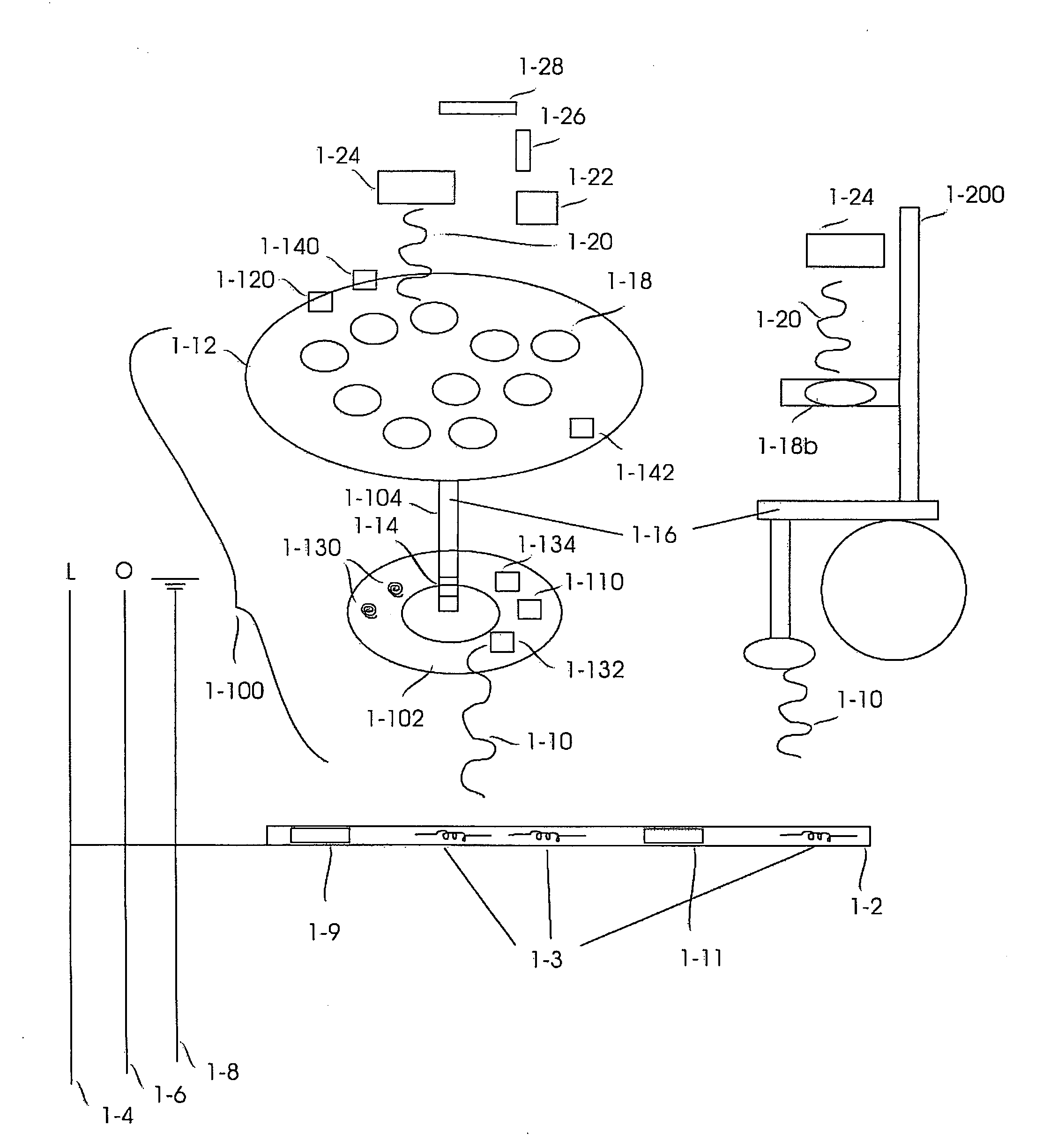
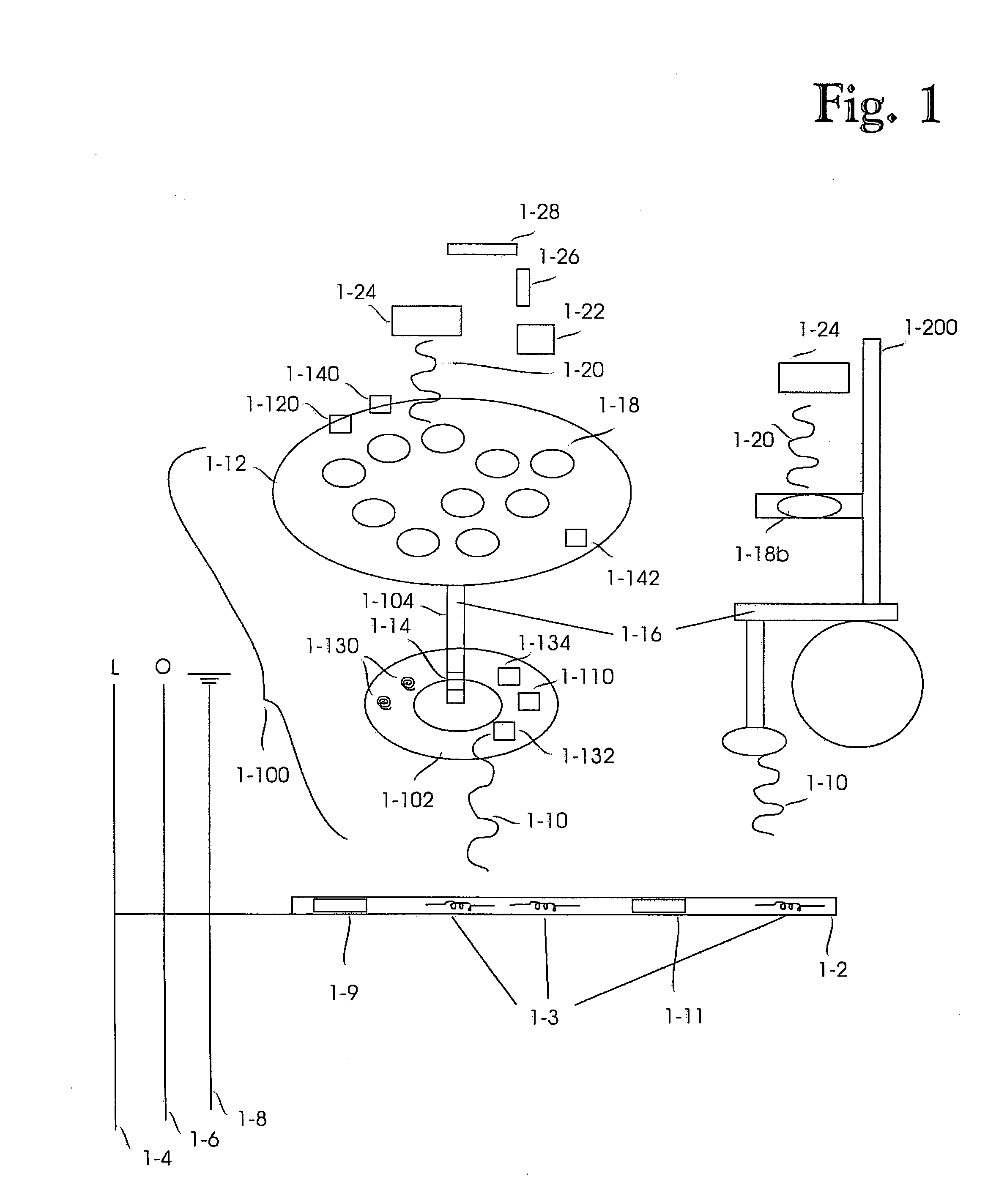
[0023]In the following, an arrangement for a completely wireless, e.g. two-phase, energy transfer will be described. The presented characteristics will be described only to the extent they are relevant for the disclosure and implementation of the invention and the preferred embodiments thereof.

[0024]The invention and its embodiments are not restricted to a particular method of use, user, terminal device, number of energy transfer surfaces, shape, size, weight, outer appearance, structure, attachment mechanism, arrangement, integration, distance or reciprocal location etc., furnishing element, energy transfer surface, method of user or equipment identification, energy transfer method, power transfer method or charging method.

[0025]Consequently, the terminal device may be a device, such as a mobile station, communicator, navigator, toy, household apparatus, handicraft tool, computer, camera, musical device, hygiene device, therapeutic device, lighting fixture, lamp or toothbrush, that...


PUM


Abstract

A energy transfer arrangement including a first energy surface, a second energy surface, first means for transferring energy from the first energy surface to the second energy surface, and second means for transferring energy from the second energy surface to a terminal device.

Description

BACKGROUND OF THE INVENTION[0001]The invention relates to an energy transfer arrangement and an energy transfer method, and particularly to a simplified energy transfer arrangement.PRIOR ART[0002]According to the prior art, the storage of electric current of battery-operated electrical devices has been controlled manually. A user noticing a drop in current searches for a charging unit consisting of a transformer, an electric conductor and a contact plug. Next, the user searches for a suitable wall socket and connects the device to the mains, whereby the charging of the device begins. When the need for charging or the possibility for it no longer exists, the user detaches the device from the mains.[0003]Conventional use of charging units and wall sockets often involves a number of disturbing and inconvenient factors: wall sockets are not always nearby in an optimal manner; the charging equipment may be misplaced, the charging equipment at hand only recharges specific products, the us...

Claims


Application Information

Patent Timeline
IPC IPC(8): H02J17/00
CPCH02J5/005H02J17/00H02J7/025H02J50/12H02J50/402H02J7/0042H02J50/80H02J50/10H02J50/20H02J50/30H02J50/40H02J50/005
Inventor ITKONEN, MAIJA
Owner POWERMAT TECHNOLOGIES
Why Eureka
Try Eureka