
Magnetic resonance imaging apparatus and magnetic resonance imaging method

a magnetic resonance imaging and magnetic resonance imaging technology, applied in the field of magnetic resonance imaging, can solve problems such as overshoots or undershoots of rf amplifiers in generating

Active Publication Date: 2010-12-09
TOSHIBA MEDICAL SYST CORP
View PDF9 Cites 12 Cited by
  • Summary
  • Abstract
  • Description
  • Claims
  • Application Information

AI Technical Summary

Benefits of technology

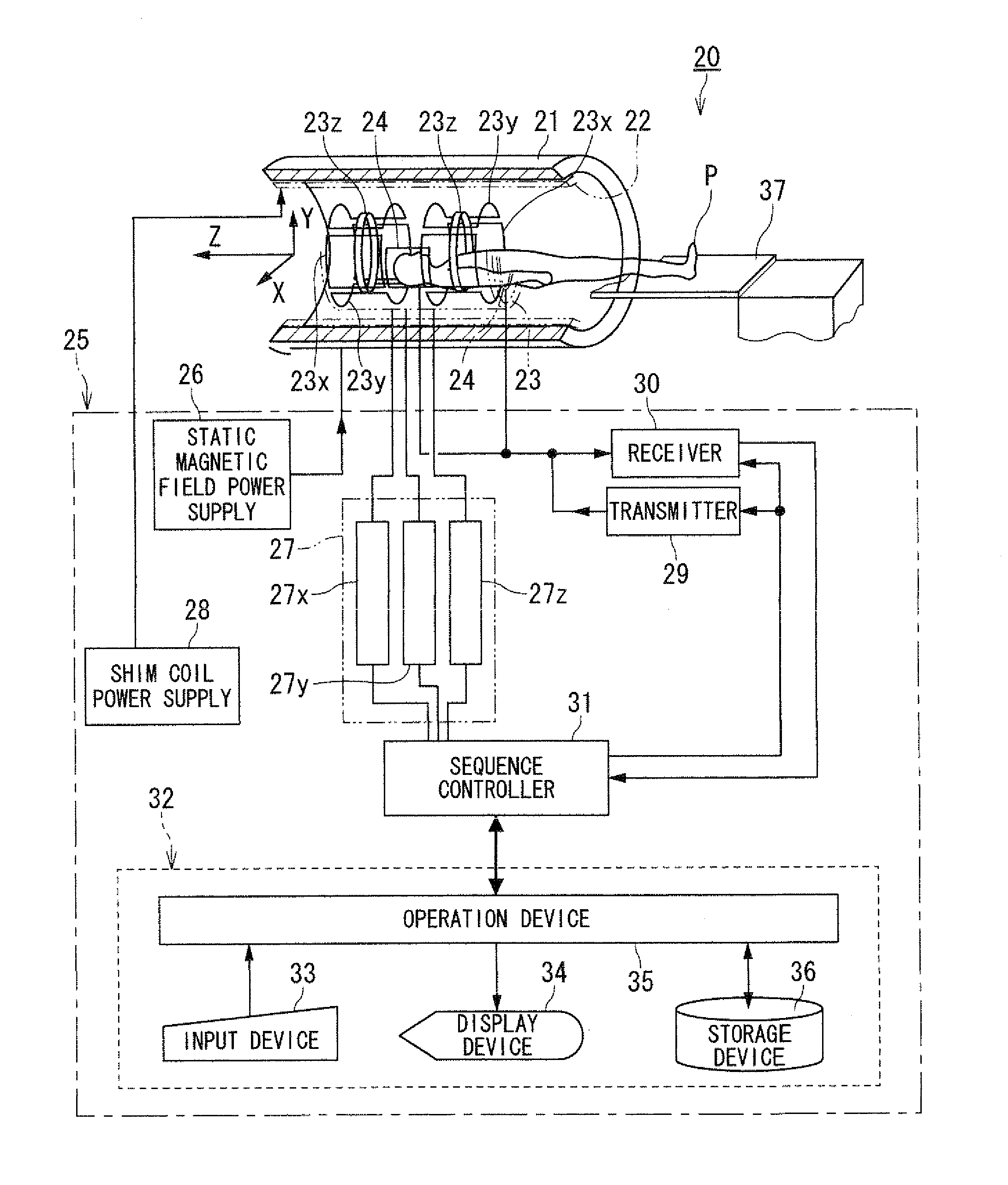
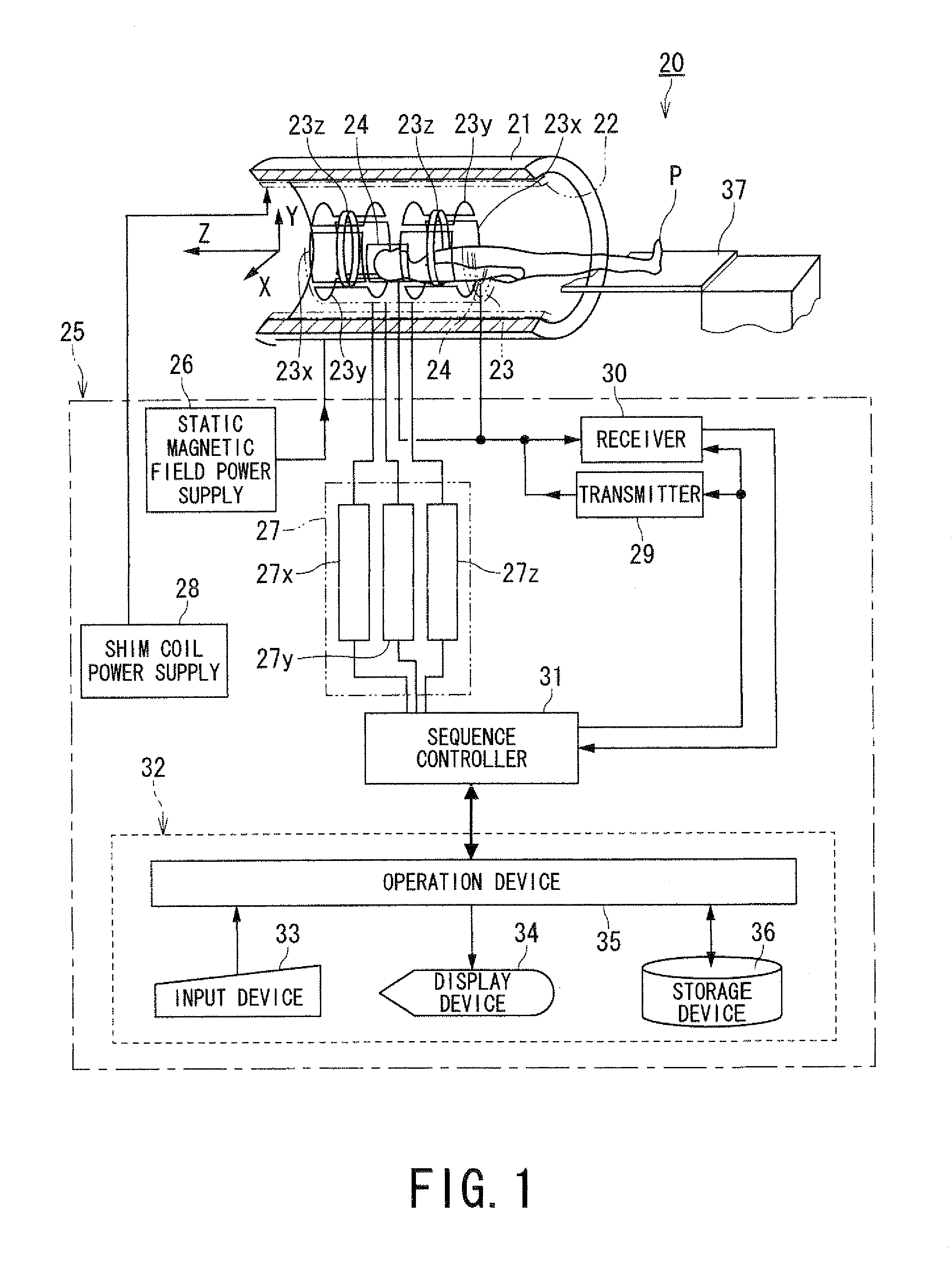
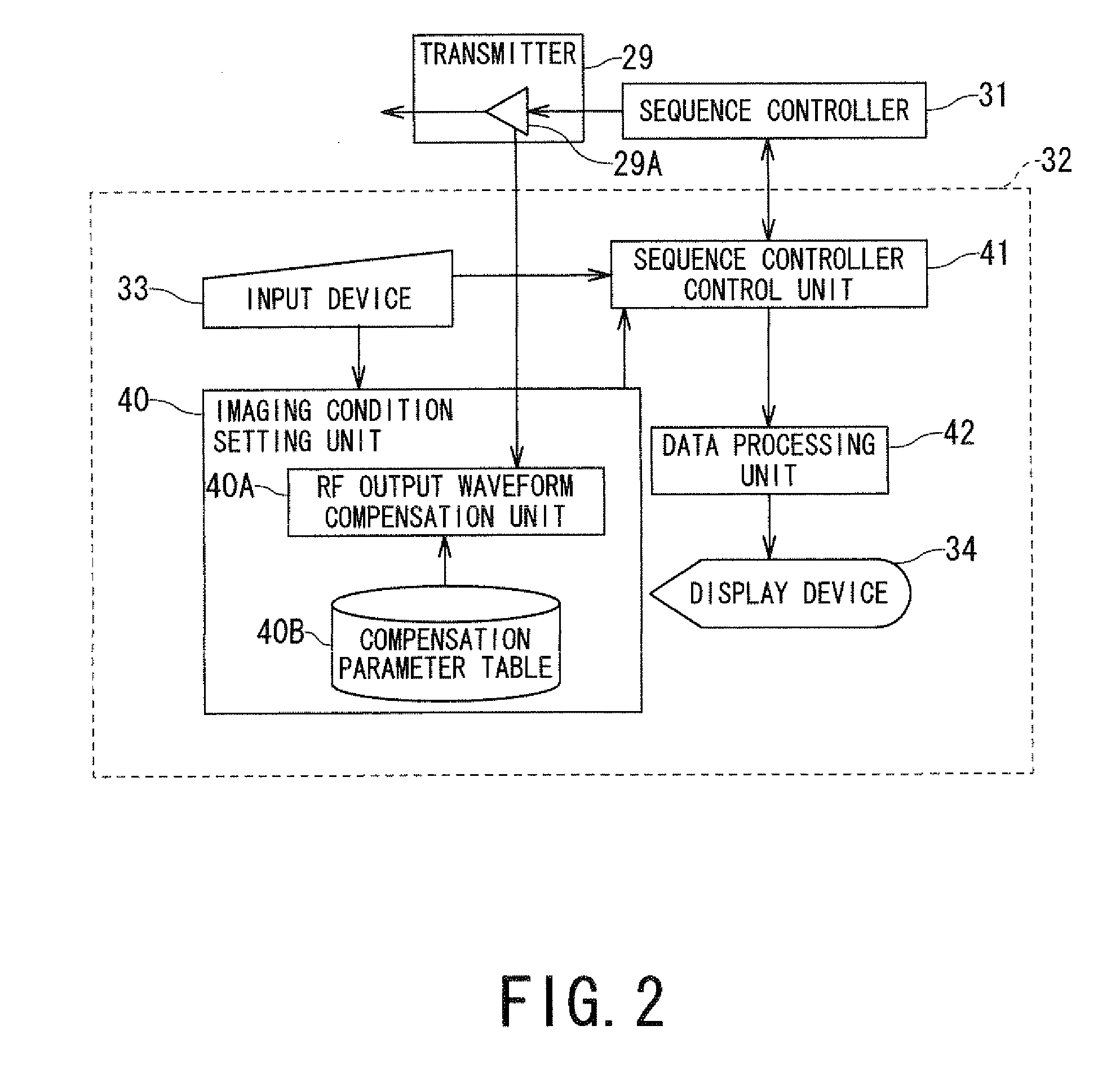
[0004]Embodiments described herein also relate generally to technology for generating an intended RF output waveform in a magnetic resonance imaging apparatus and a magnetic resonance imaging method.

Problems solved by technology

However, an RF amplifier overshoots or undershoots failing in generating a predetermined waveform of an RF transmission pulse precisely in some cases, when imaging is performed under a pulse sequence including an RF transmission pulse with a drastic gradient (slope) such as a square-wave pulse like a pulse sequence using the VFA method, the VERSE method or the tag pulse.

Method used


Image

  • Magnetic resonance imaging apparatus and magnetic resonance imaging method
  • Magnetic resonance imaging apparatus and magnetic resonance imaging method
  • Magnetic resonance imaging apparatus and magnetic resonance imaging method

Examples


Embodiment Construction

[0019]The following embodiments aim to provide MRI technology which can generate an intended waveform of an RF output pulse more stably than the conventional art, but the present invention is not limited to this aim.

[0020]According to one embodiment, a magnetic resonance imaging apparatus includes an acquiring unit and a generating unit. The acquiring unit performs compensation of a control waveform of a radio-frequency wave based on “an output waveform of a radio-frequency wave from an amplifier before the compensation” so that an intended output waveform of a radio-frequency wave for generating a spatially non-selective radio-frequency magnetic field is outputted from the amplifier, and acquires a magnetic resonance signal using the control waveform of a radio-frequency wave after the compensation. The generating unit generates image data based on the magnetic resonance signal.

[0021]According to one embodiment, a magnetic resonance imaging method includes the steps of:

[0022](a) pe...


PUM


Abstract

According to one embodiment, a magnetic resonance imaging apparatus includes an acquiring unit and a generating unit. The acquiring unit performs compensation of a control waveform of a radio-frequency wave based on “an output waveform of a radio-frequency wave from an amplifier before the compensation” so that an intended output waveform of a radio-frequency wave for generating a spatially non-selective radio-frequency magnetic field is outputted from the amplifier, and acquires a magnetic resonance signal using the control waveform of a radio-frequency wave after the compensation. The generating unit generates image data based on the magnetic resonance signal.

Description

CROSS-REFERENCE TO RELATED APPLICATION(S)[0001]This application is based upon and claims the benefit of priority from Japanese Patent Application No. 2009-135100 filed on Jun. 4th 2009 and Japanese Patent Application No. 2010-112166 filed on May 14 2010; The entire contents of which are incorporated herein by reference.BACKGROUND OF THE INVENTION[0002]1. Field of the Invention[0003]Embodiments described herein relate generally to MRI (magnetic resonance imaging) which magnetically excites nuclear spin of an object with an RF (radio frequency) signal having the Larmor frequency and reconstructs an image based on NMR (nuclear magnetic resonance) signals generated due to the excitation.[0004]Embodiments described herein also relate generally to technology for generating an intended RF output waveform in a magnetic resonance imaging apparatus and a magnetic resonance imaging method.[0005]2. Description of the Related Art[0006]Magnetic Resonance Imaging is an imaging method which magneti...

Claims


Application Information

Patent Timeline
IPC IPC(8): G01R33/44
CPCG01R33/5659G01R33/3607
Inventor UMEDA, MASAAKISOEJIMA, KAZUYUKI
Owner TOSHIBA MEDICAL SYST CORP
Learn More