Method and system for configuring a leaky wave antenna utilizing micro-electro mechanical systems

a technology of micro-electro mechanical systems and leaky wave antennas, applied in the field of wireless communication, can solve the problems of power inefficiency of transmitters and/or receivers in comparison to other blocks of portable communication devices

Inactive Publication Date: 2010-12-09
AVAGO TECH INT SALES PTE LTD
View PDF103 Cites 47 Cited by
  • Summary
  • Abstract
  • Description
  • Claims
  • Application Information

AI Technical Summary

Benefits of technology

[0011]A system and/or method for configuring a leaky wave antenna utilizing micro-electro mechanical systems as...

Problems solved by technology

Additionally, transmit and/or receive circuitry within such mobile wireless devices often account for a significant portion of the power consumed within these devices.
Mor...

Method used


Image

  • Method and system for configuring a leaky wave antenna utilizing micro-electro mechanical systems
  • Method and system for configuring a leaky wave antenna utilizing micro-electro mechanical systems
  • Method and system for configuring a leaky wave antenna utilizing micro-electro mechanical systems

Examples


Embodiment Construction

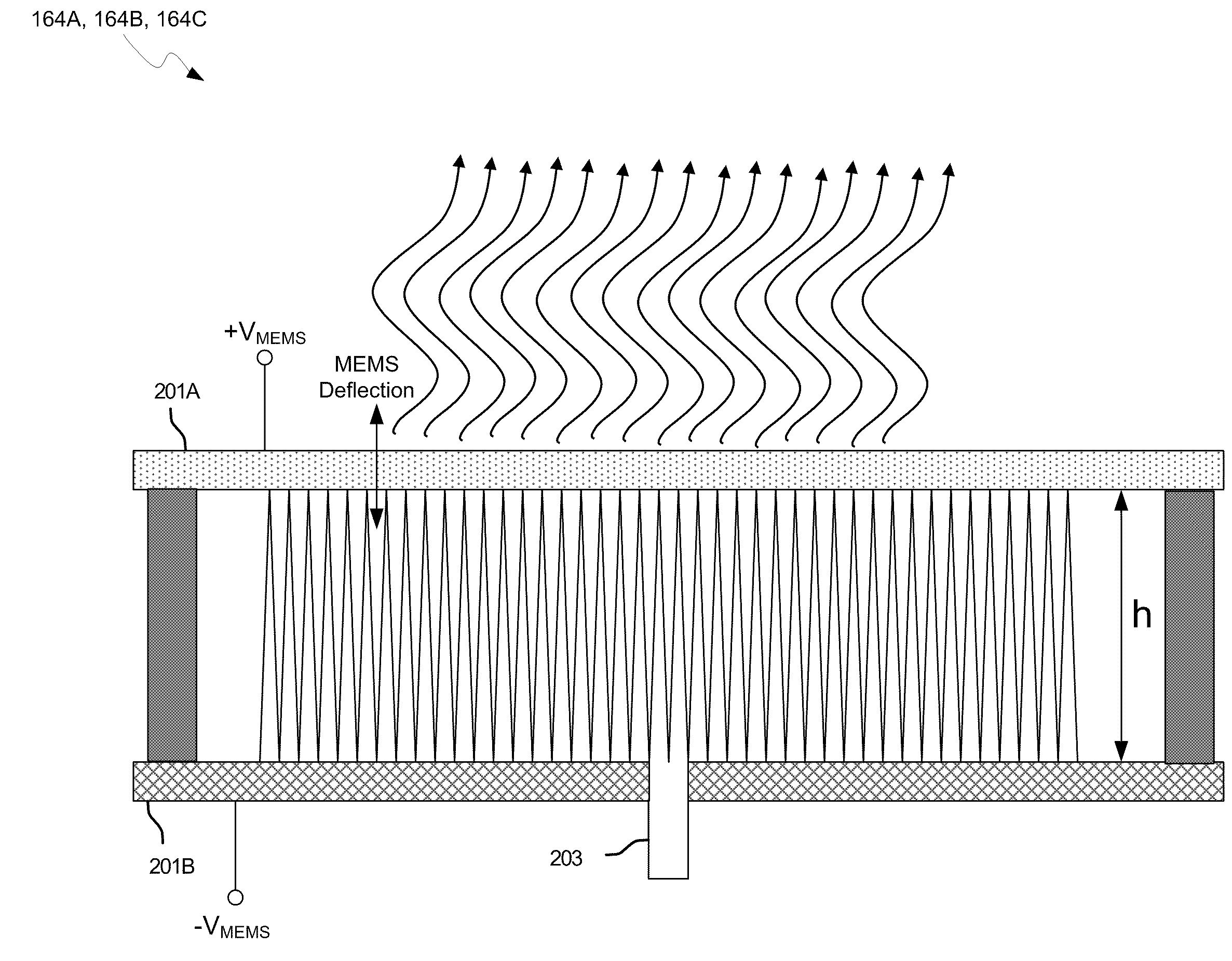
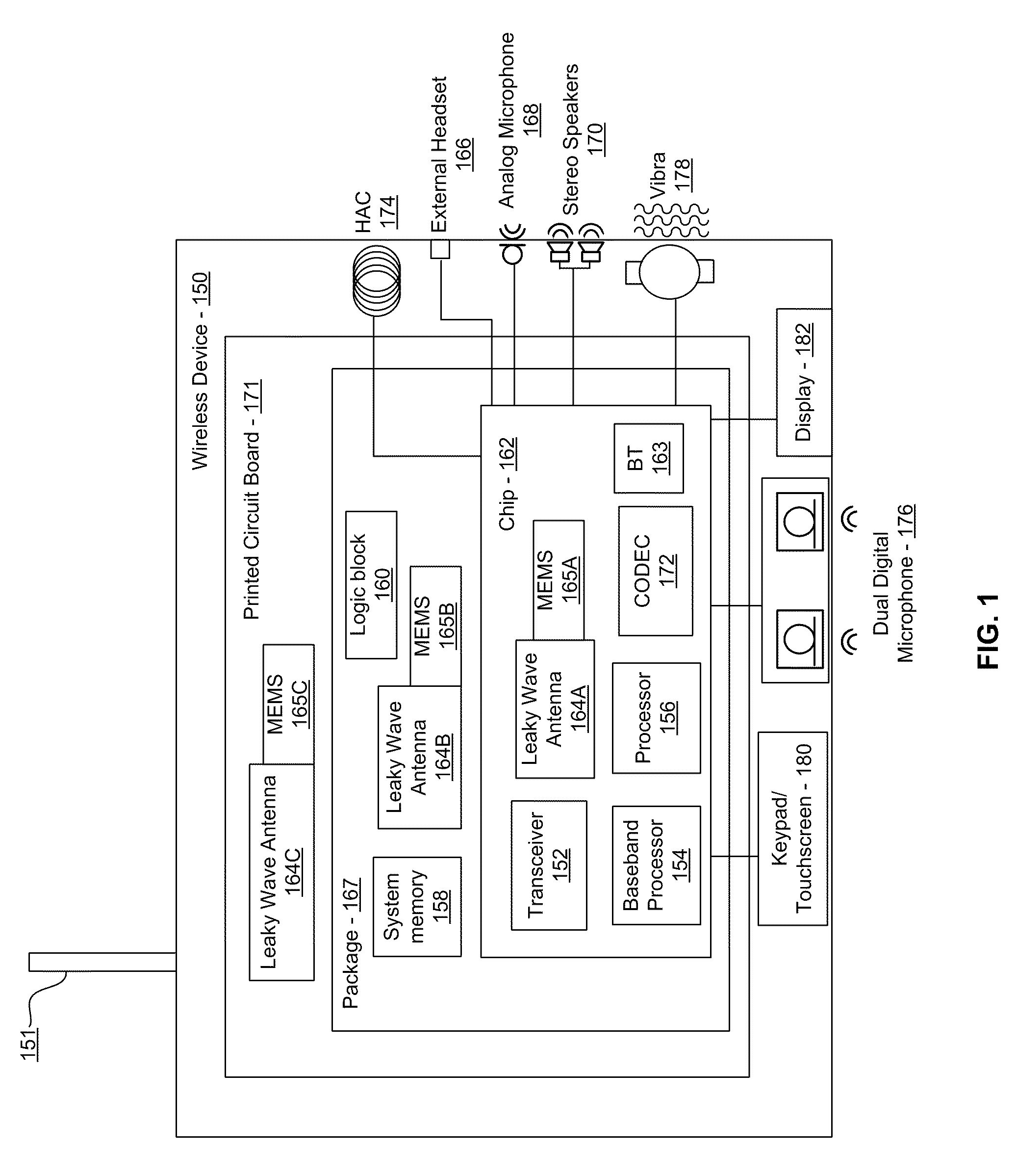
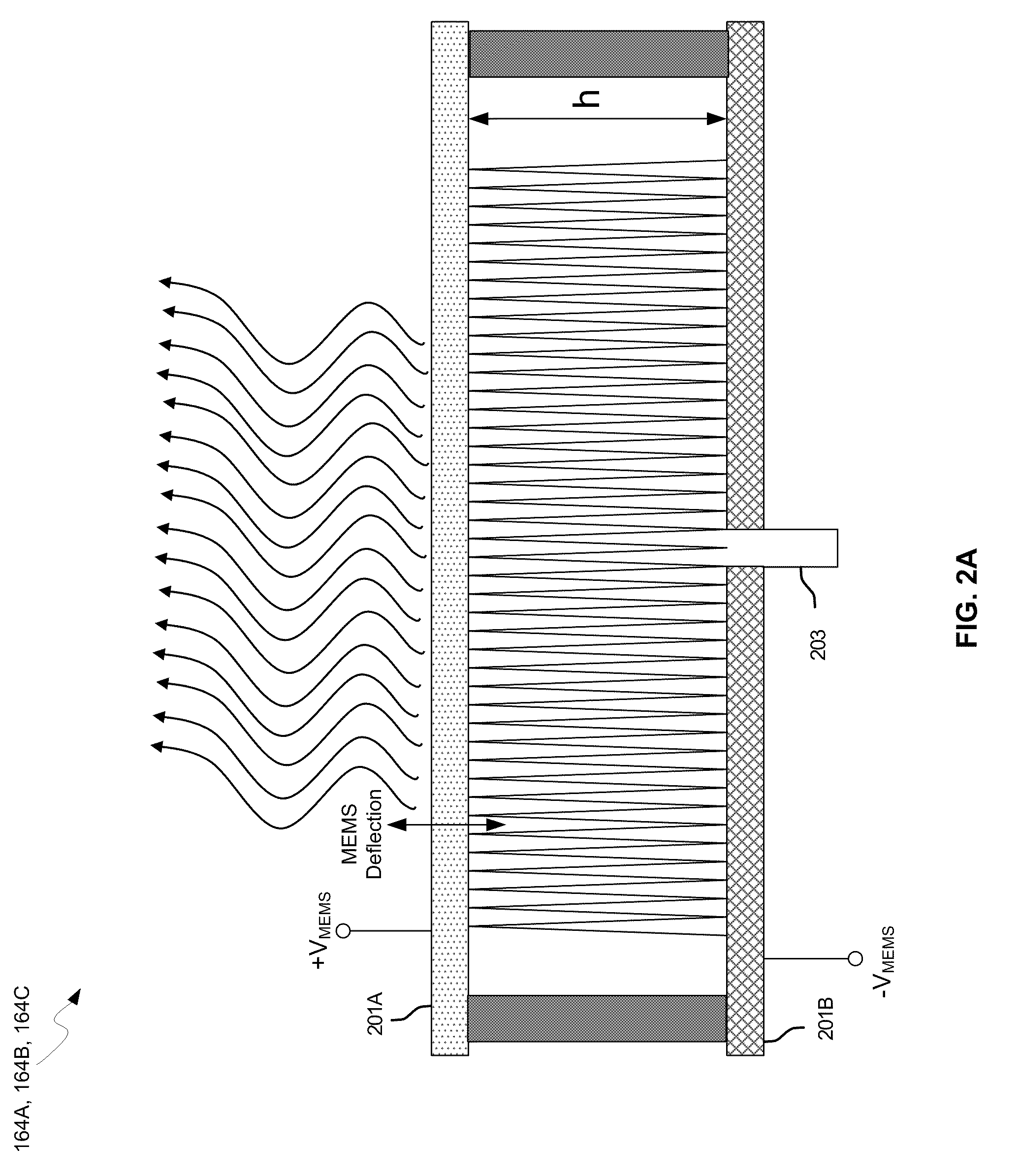
[0024]Certain aspects of the invention may be found in a method and system for configuring a leaky wave antenna (LWA) utilizing micro-electromechanical systems (MEMS). Exemplary aspects of the invention may comprise configuring a resonant frequency of one or more LWAs in a wireless device utilizing MEMS actuation. RF signals may be communicated using the one or more LWAs. The one or more leaky wave antennas may be integrated in metal layers in a chip, an integrated circuit package, and / or a printed circuit board in the wireless device. The leaky wave antennas may comprise microstrip waveguides where a cavity height of the LWAs may be dependent on a spacing between conductive lines in the microstrip waveguides. The LWAs may be configured to transmit the wireless signals at a desired angle from a surface of the LWA. The integrated circuit package may be affixed to a printed circuit board and an integrated circuit may be flip-chip-bonded to the integrated circuit package. An air gap ma...


PUM


Abstract

Methods and systems for configuring a leaky wave antenna (LWA) utilizing micro-electromechanical systems (MEMS) are disclosed and may include configuring a resonant frequency of one or more LWAs in a wireless device utilizing MEMS actuation. RF signals may be communicated using the LWAs. The LWAs may be integrated in metal layers in a chip, an integrated circuit package, and/or a printed circuit board in the wireless device. The LWAs may include microstrip waveguides where a cavity height of the LWAs may be dependent on a spacing between conductive lines in the microstrip waveguides. The LWAs may be configured to transmit the wireless signals at a desired angle. The integrated circuit package may be affixed to a printed circuit board and an integrated circuit may be flip-chip-bonded to the integrated circuit package. An air gap may be integrated adjacent to one or more of the metal layers for the MEMS actuation.

Description

CROSS-REFERENCE TO RELATED APPLICATIONS / INCORPORATION BY REFERENCE[0001]This application makes reference to, claims the benefit from, and claims priority to U.S. Provisional Application Ser. No. 61 / 246,618 filed on Sep. 29, 2009, and U.S. Provisional Application Ser. No. 61 / 185,245 filed on Jun. 9, 2009.[0002]This application also makes reference to:U.S. patent application Ser. No. 12 / 650,212 filed on Dec. 30, 2009;U.S. patent application Ser. No. 12 / 650,295 filed on Dec. 30, 2009;U.S. patent application Ser. No. 12 / 650,277 filed on Dec. 30, 2009;U.S. patent application Ser. No. 12 / 650,192 filed on Dec. 30, 2009;U.S. patent application Ser. No. 12 / 650,224 filed on Dec. 30, 2009;U.S. patent application Ser. No. 12 / 650,176 filed on Dec. 30, 2009;U.S. patent application Ser. No. 12 / 650,246 filed on Dec. 30, 2009;U.S. patent application Ser. No. 12 / 650,292 filed on Dec. 30, 2009;U.S. patent application Ser. No. 12 / 650,324 filed on Dec. 30, 2009;U.S. patent application Ser. No. 12 / 708,36...

Claims


Application Information

Patent Timeline
IPC IPC(8): H01Q13/20
CPCH01Q1/2283H01Q13/22H04B5/0031H01Q15/006G01S13/06H01Q13/20H04B1/04H04B7/24H04B1/0458H01L2224/16225H01L2224/32225H01L2224/73204H01L2924/13091H01L2924/00G06K7/10316H01Q15/0066H01Q15/23H01Q19/06
Inventor ROFOUGARAN, AHMADREZA
Owner AVAGO TECH INT SALES PTE LTD
Why Eureka
Try Eureka