
Method and device for data relay transmission in wireless relay network

a wireless relay and wireless relay technology, applied in the field of wireless relay communication, can solve the problems of large latency of relay transmission, increase of data from the source to the destination, through the transmission via multiple relay stations, etc., and achieve the effect of improving the qos service performance of the relay station and canceling the waiting latency

Active Publication Date: 2010-12-09
ALCATEL LUCENT SAS
View PDF3 Cites 18 Cited by
  • Summary
  • Abstract
  • Description
  • Claims
  • Application Information

AI Technical Summary

Benefits of technology

The invention provides a method and device for data relay transmission in a wireless relay communication network to address the problem of latency. The method includes obtaining egress CID related information from input MAC PDUs, generating output MAC PDUs with the egress CID related information, and performing QoS scheduling for the output MAC PDUs based on a predefined rule. This simplifies the data processing procedure of the relay station and reduces latency in relay transmission. The device includes an obtaining means, a generator, and an output means. The technical effect of the invention is to improve the performance of the relay station and decrease latency in relay transmission.

Problems solved by technology

Thus, the controlling of latency, as well as the decreasing of latency as possible, are very important issues, and are the pursuit for those skilled in the art all the time.
In this procedure, the de-cascade, de-segmenting or de-capsulating the MAC PDUs in order to obtain MAC SDUs is one main cause to the latency of relay transmission.
It is apparent that the above waiting latency will become worse with the increase of the number of relay hops and the number of segmentations of the divided MAC SDU, which causes that the latency of the data from the source to the destination, through the transmission via multiple relay stations, will increase by a large degree.

Method used


Image

  • Method and device for data relay transmission in wireless relay network
  • Method and device for data relay transmission in wireless relay network
  • Method and device for data relay transmission in wireless relay network

Examples


first embodiment

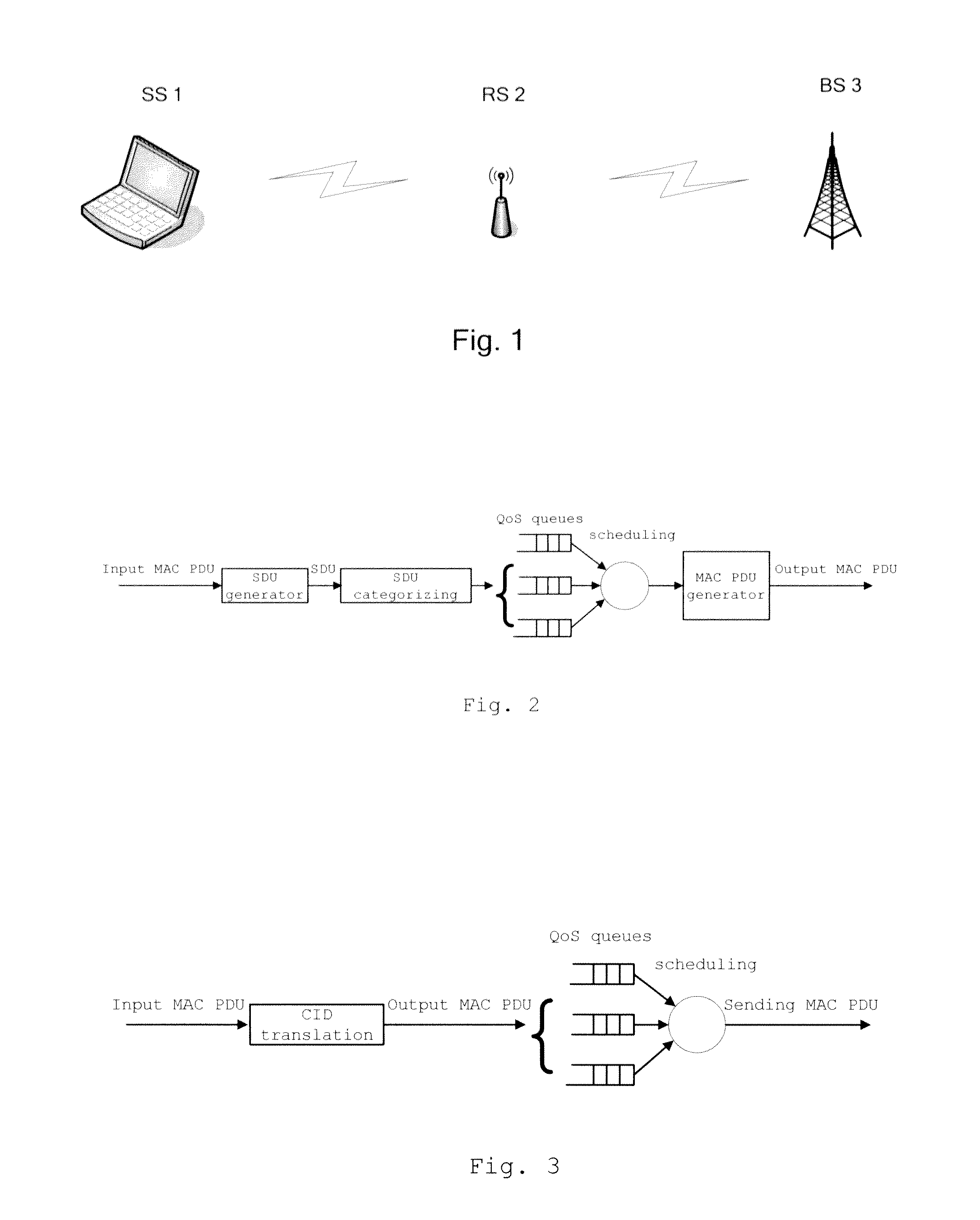
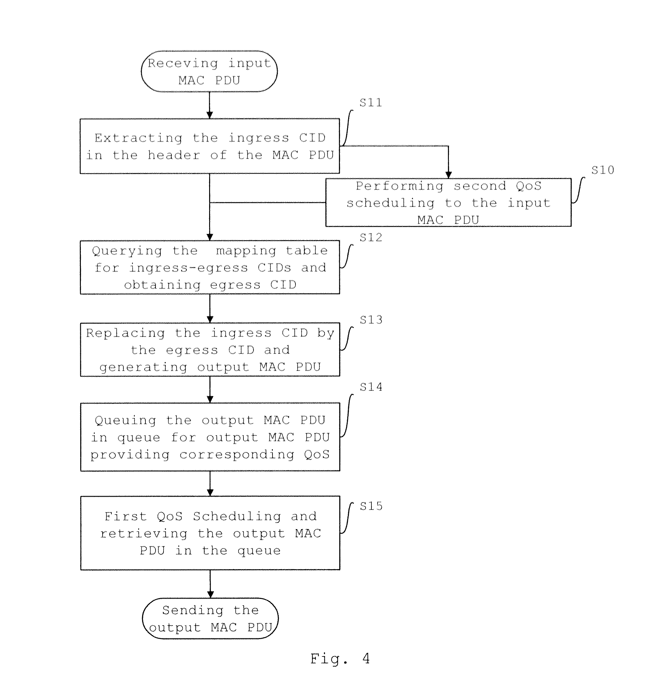
[0032]FIG. 4 is a flowchart of the method for data relay transmission in relay stations, according to the invention. The invention will be described in the following part in details by referring to this figure accompanied with FIG. 1 and FIG. 3.

[0033]Specifically, in step S11, the RS extracts the ingress CID information, such as ingress CID=0x18, from the header of the input MAC PDG, which entered the RS;

[0034]After that, in step S12, the RS takes the extracted ingress CID=0x18 as an index, and queries a mapping table for ingress-egress CIDs, which is pre-stored in the RU, so as to obtain the egress CID corresponding to the ingress CID.

[0035]Wherein, the mapping table for ingress-egress CIDs is a mapping table stored in the RS, which identifies the mapping relationship from one or more ingress CIDs to one or more egress CIDs. The table comprises an ingress CID list and an egress CID list, and defines the mapping relationship from ingress CID to egress CID. According to the number of...

second embodiment

[0047]FIG. 8 is a flowchart of the method for data relay transmission in relay stations, according to the invention. The invention will be described in the following part in details by referring to this figure accompanied with FIG. 1 and FIG. 3.

[0048]Specifically, in this embodiment, step S21 and step S22 are the same as step S11 and step 112 in the if first embodiment, and will not be described here. For example, the ingress CID-0x18 the input MAC 000 header is extracted via step 121, and egress CID-0x3f is obtained via step S22.

[0049]After that, the relay station uses the method of tunneling encapsulation, and adds a new header to the input MAC Pal for tunneling encapsulation. As shown in FIG. 9, the relay station embeds the egress CID-0x3f into the new header after the encapsulation, so as to generate an encapsulated output MAC PDU. In case that correction bits (including HCS for header correction and / or CRC data correction bits) is contained in the MAC PDU, it is necessary to re...

third embodiment

[0050]FIG. 10 is a flowchart of the method for data relay transmission in relay stations, according to the invention. The invention will be described in the following part in details by referring to this figure accompanied with FIG. 1 and FIG. 3.

[0051]The subheader of the input MAC PDU comprises a group of CIDs, which includes one or more egress CIDs corresponding to one or more relay hops of the transmission path for the input MAC PDU. In step S31, the relay station extracts the ingress CID information from the header of the input MAC. PDU, and extracts the group of CIDs from the subheader of the input MAC PDU. The extracted group of CIDs includes one or more egress CIDs corresponding to one or more relay hops of the transmission path for the input MAC PDU.

[0052]After that, in step S32, the relay station extracts the CID corresponding to the present relay hop from the group of CIDs, and takes this CID as the egress CID.

[0053]Then, in step S33, the relay station moves the ingress CI...


PUM


Abstract

A method and a device for data relay transmission in a wireless relay communication network are provided, in which, the relay station directly obtains corresponding egress CID related information based on input MAC PDUs, then generates output MAC PDUs including the egress CID related information, and at last, according to the egress CID related information, performs QoS scheduling for the output MAC PDUs, so as to output them in an sequence of QoS. The invention omits the steps of de-cascading, de-segmenting or de-capsulating the MAC PDUs in order to obtain MAC SDUs, and the steps of scheduling by category, cascading, segmenting, and encapsulating the MAC SDUs in order to re-generate the MAC PDUs in the prior art, and the invention simplifies the data processing procedure and achieves the goal of decreasing the relay latency. Preferably, before the relay station generates the output MAC PDUs based on the input MAC PDUs, it can also schedule the input MAC PDUs based on the ingress CID information therein, so as to further improve the QoS service performance.

Description

TECHNICAL FIELDS[0001]The invention relates to wireless relay communication, particularly relates to the relay station in wireless relay communication network.BACKGROUND OF THE INVENTION[0002]The WiMAX technology, based on the IEEE 802.16 standard, supports both fixed (802.16d) and mobile (802.16e) broad band wireless access. It provides new solution to solve the “last mile” of broad band data access, and it is expected to be a very promising technical solution in the next generation wireless broad band access network. As to the communication network, the latency a always considered as one of the most key factors to the performance of the network, and it is also applicable for the WiMAX systems which provide mechanisms for QoS guarantee. The IEEE 802.16 standard defines 5 different types for scheduled service, in order to provide differentiated QoS services, and these types for scheduled service comprise: unsolicited grant service (UGS), real-time polling service (rtPS), extended re...

Claims


Application Information

Patent Timeline
Patent Type & Authority Applications(United States)
IPC IPC(8): H04L12/26
CPCH04L47/6215H04B7/155
Inventor WANG, DONGYAOZOU, WEIJIN, SHAN
Owner ALCATEL LUCENT SAS
Learn More