Battery pack

a battery pack and battery technology, applied in the field of batteries, can solve the problems that batteries have needed to be easily maintained, and achieve the effect of accurately positioning the partition plate, easy positioning, and reducing the number of batteries

Inactive Publication Date: 2010-12-09
INDONESIA STOCK EXCHANGE
View PDF2 Cites 2 Cited by
  • Summary
  • Abstract
  • Description
  • Claims
  • Application Information

AI Technical Summary

Benefits of technology

[0007]In the battery pack of the invention, a groove-like portion is provided at an end-edge of the opened lateral surface of the upper housing so as to attach thereto and remove therefrom the lid body by linearly sliding the lid body along a circumferential direction, and a recessed portion is provided at an end-edge of the opened lateral surface of the lower housing so as to be able to be fitted to a small projecting portion provided on the lid body. Thus, the lid body can easily be moved along the edge of the open lateral surface, can easily be positioned and can be made hard to disengage.
[0008]In the battery pack of the invention, a taking-out tub portion is provided on the opened lateral surface side of the partition plate so as to rise therefrom. This tub portion can control the release of the battery cartridge. For example, if the tub portion is configured to face the rear cover side, it usually restrains the movement of the battery cartridge mounted on the substrate cover and makes it possible for the battery cartridge to be freely movable only when the lid body is removed.
[0009]In the battery pack of the invention, a positioning projecting portion is provided on the partition plate so as to be abutted against an inner surface of a top surface of the top cover. This projecting portion and the projecting portion of the substrate cover described earlier can accurately position the partition plate so that the battery cartridge-storing space can accurately be defined inside the housing.
[0010]In the battery pack of the invention, an electrical and mechanical portion to be connected to other equipment such as a TV camera is provided on a rear surface of the rear cover and one lateral surface, and an inclined surface is provided at both lateral edges of the rear cover to prevent interference with the other equipment such as a TV camera. Other equipment such as a TV camera is formed with various projections due to some convenience for the manufacturer thereof. In particular, projections adapted to restrict the lateral surface position of the battery pack often hinder another company's equipment from being attached. However, since the inclined surface portion is provided, situations of avoiding such hindrance increase.
[0011]The battery pack of the present invention has effects such that the cartridge-like batteries can simply be attached and removed, use of a plurality of the batteries can achieve high-capacity and operation such as the attachment-removal and replacement of the battery can be facilitated.

Problems solved by technology

The covers joined together by ultrasound welding or the like can make the battery pack staunch; however, the covers cannot be opened in the event that the battery cell incorporated may cause trouble or the like.
Because of relatively expensive, the battery pack has needed to be easily maintained.

Method used


Image

  • Battery pack
  • Battery pack
  • Battery pack

Examples


embodiment

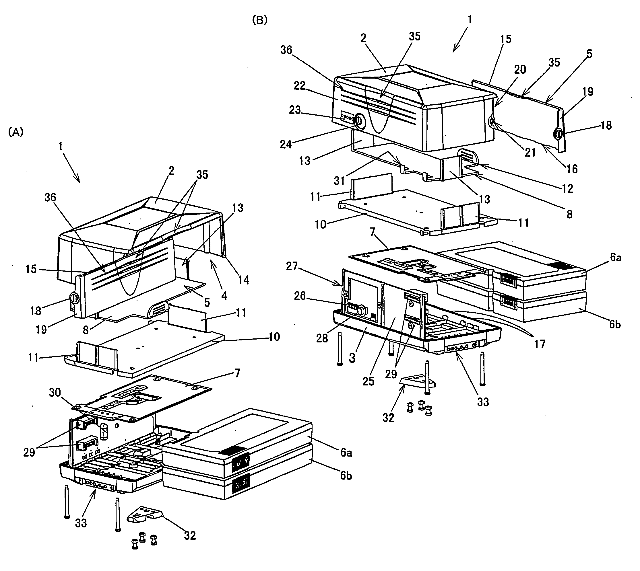
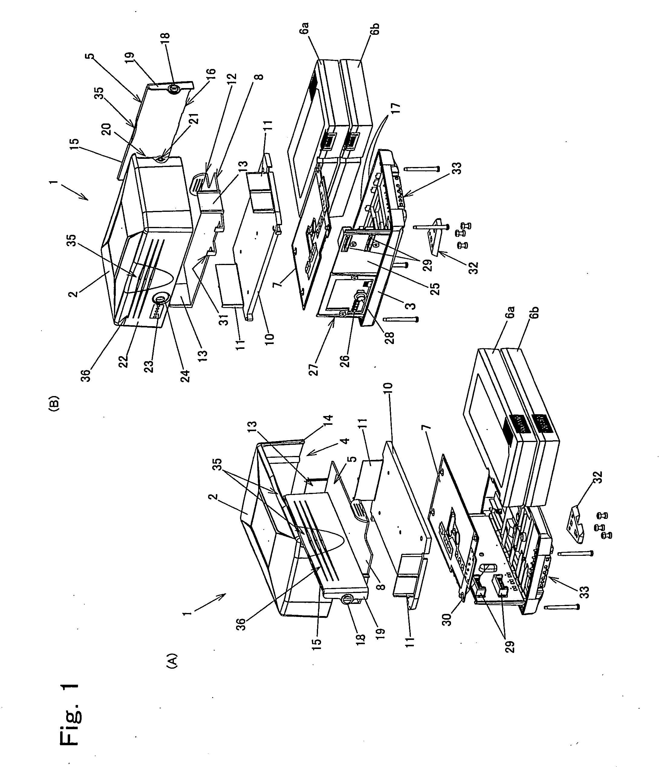
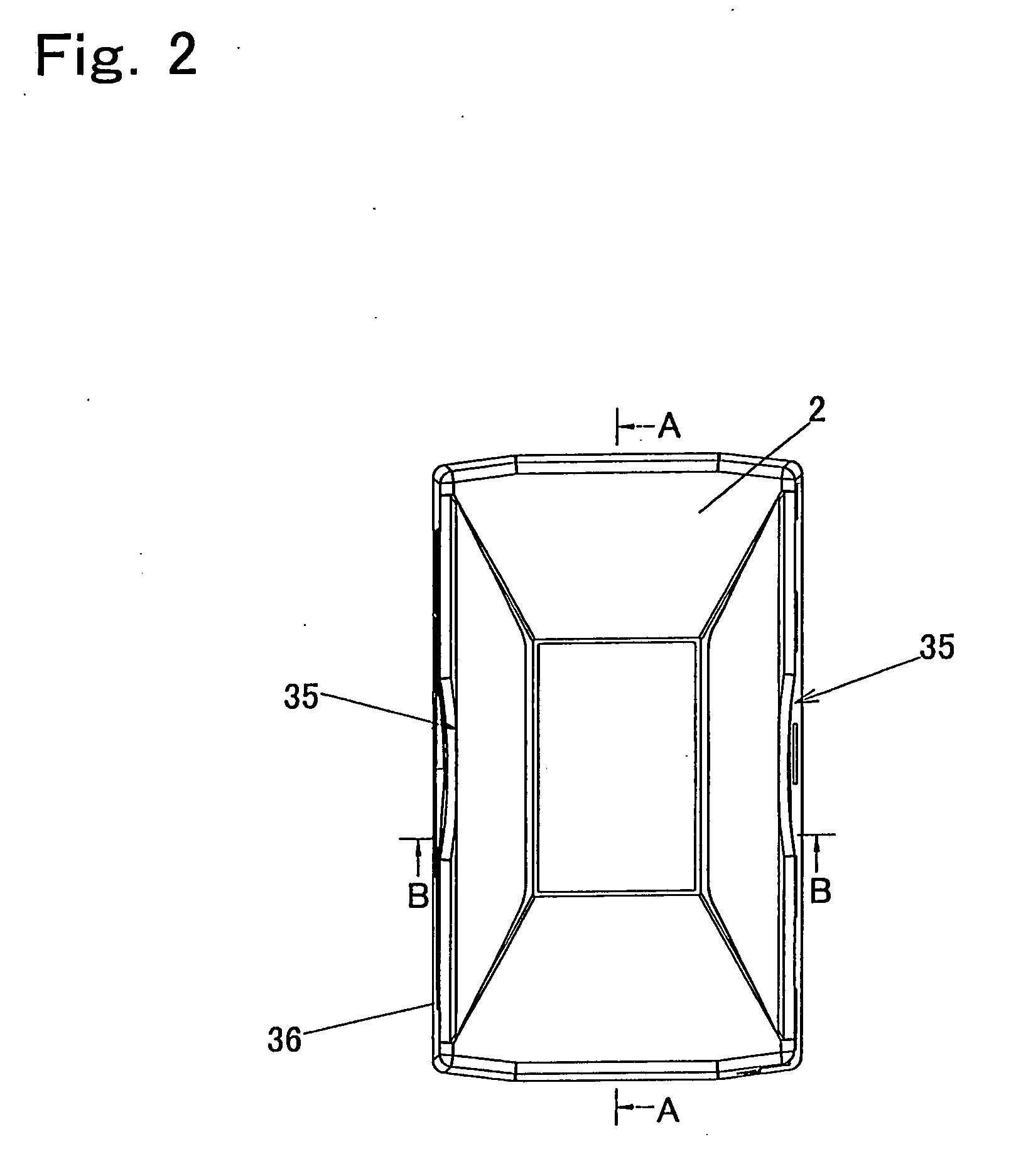
[0068]FIG. 1 is an exploded perspective view of a battery pack according to an embodiment of the present invention. A battery pack 1 of the present embodiment mainly includes a top cover 2, a rear cover 3, a slide cover 5, and a plurality of cartridge-like batteries (hereinafter, referred to as the battery cartridges) 6a and 6b. The top cover 2 with four circumferential lateral surfaces one of which is opened and the rear cover 3 constitute a housing. The slide cover 5 serves as a lid body that opens and closes an open lateral surface 4 of the housing constituted by the top cover 2 and rear cover 3. The battery cartridges 6a, 6b are removably attached to the inside of the housing constituted by the top cover 2 and rear cover 3.

[0069]Specifically, the housing is formed to be divided in two portions one of which is the top cover 2 having the open lateral surface 4 and another one of the two portions is the rear cover 3 mounted with a control substrate 7 thereon. In addition, the insid...


PUM

PropertyMeasurementUnit
movementaaaaaaaaaa
electricalaaaaaaaaaa
mechanicalaaaaaaaaaa

Abstract

Two batteries are made mountable like a cartridge in a housing to achieve the large capacity of a battery pack and to improve the facilitation of operation such as replacement of a battery.
The battery pack includes covers 2, 3 having four circumferential lateral surfaces one of which is opened; a lid body 5 opening and closing the opened lateral surface 4 of the housings; and a plurality of batteries 6a, 6b attached into and removed from the inside of the housing. The housing are formed to be divided in two portions one of which is a top cover 2 having the open lateral surface, another one of the two portions being a rear cover 3 mounted with a control substrate mounted thereon. The inside of the top cover is vertically divided in two by a partition plate 8 to form battery-storing portions 9a and 9b which can store the battery cartridges 6a and 6b, respectively.

Description

TECHNICAL FIELD[0001]The present invention is relates to a battery pack in which cartridge-like batteries are stored in an attachable and removable manner.BACKGROUND ART[0002]In a large-sized video camera called one for business-use or for professional-use such as TV camera, a battery cell or a pack combining a plurality of battery cells and a substrate are stored between a rear cover and a top cover, which are secured to each other by welding, adhesive bonding, or the like, as shown in e.g. patent document 1. For example, covers divided in two are pressurized and heated by ultrasound to be melted and solidified for joining. The battery pack formed as described above has such features that it can be configured to have a simple structure and to be compact and staunch as compared with covers that are screw-fastened to each other for fixation and thus can be manufactured inexpensively.DISCLOSURE OF INVENTION[0003]The covers joined together by ultrasound welding or the like can make the...

Claims


Application Information

Patent Timeline
Patent Type & Authority Applications(United States)
IPC IPC(8): H01M2/10H01M50/209
CPCH01M2/1061H01M10/48H01M6/5044Y02E60/10H01M50/209
Inventor SATAKE, MIKIONISHIKAWA, TOMO
Owner INDONESIA STOCK EXCHANGE
Why Eureka
Try Eureka