Gain compensation device over temperature and method thereof

a compensation device and temperature technology, applied in the direction of rf amplifiers, high frequency amplifiers, transmission, etc., can solve problems such as unwanted users

Inactive Publication Date: 2010-12-09
MEDIATEK INC
View PDF7 Cites 55 Cited by
  • Summary
  • Abstract
  • Description
  • Claims
  • Application Information

AI Technical Summary

Benefits of technology

[0006]The present invention provides a gain compensation device for adjusting gain of an amplifier. Gain of the amplifier is controlled by signals on a gain control end of the amplifier. The gain compensation device comprises a temperature compensation generator, an adder, and a temperature sensor. The temperature compensation generator is for generating an additional gain parameter according to a reference temperature, a current temperature, and a temperature coefficient. The adder comprises a first input end, coupled to the temperature compensation generator for receiving the additional gain parameter, a second input end for receiving a default gain parameter, and an output end coupled to the gain control end of the amplifier for outputting sum of the additional gain parameter and the default gain parameter. The temperature sensor is for providing the current temperature.
[0007]The present invention further provides a RF transmitter. The RF transmitter comprises an RF module, and a temperature compensation amplifying module. The RF module comprises a local oscillator for providing a clock signal, a divider coupled to the clock signal into a first divided clock signal and a second divided clock signal, a first mixer for receiving an I-path base-band signal and the first divided clock signal and accordingly generating an in-phase signal, a second mixer for receiving a Q-path base-band signal and the second divided clock signal and accordingly generating a quadrature-phase signal, a first adder for receiving the in-phase signal and the quadrature-phase signal and accordingly generating an output signal. The first divided clock signal and the second divided clock signal are different by 90 degrees in phase. The temperature compensation amplifying module comprises a gain compensation device, and an amplifier. The gain compensation device comprises a temperature compensation generator for generating an additional gain parameter according to a reference temperature, a current temperature, and a temperature c

Problems solved by technology

In other words, the power of the output signal SOUT does not r

Method used


Image

  • Gain compensation device over temperature and method thereof
  • Gain compensation device over temperature and method thereof
  • Gain compensation device over temperature and method thereof

Examples


Embodiment Construction

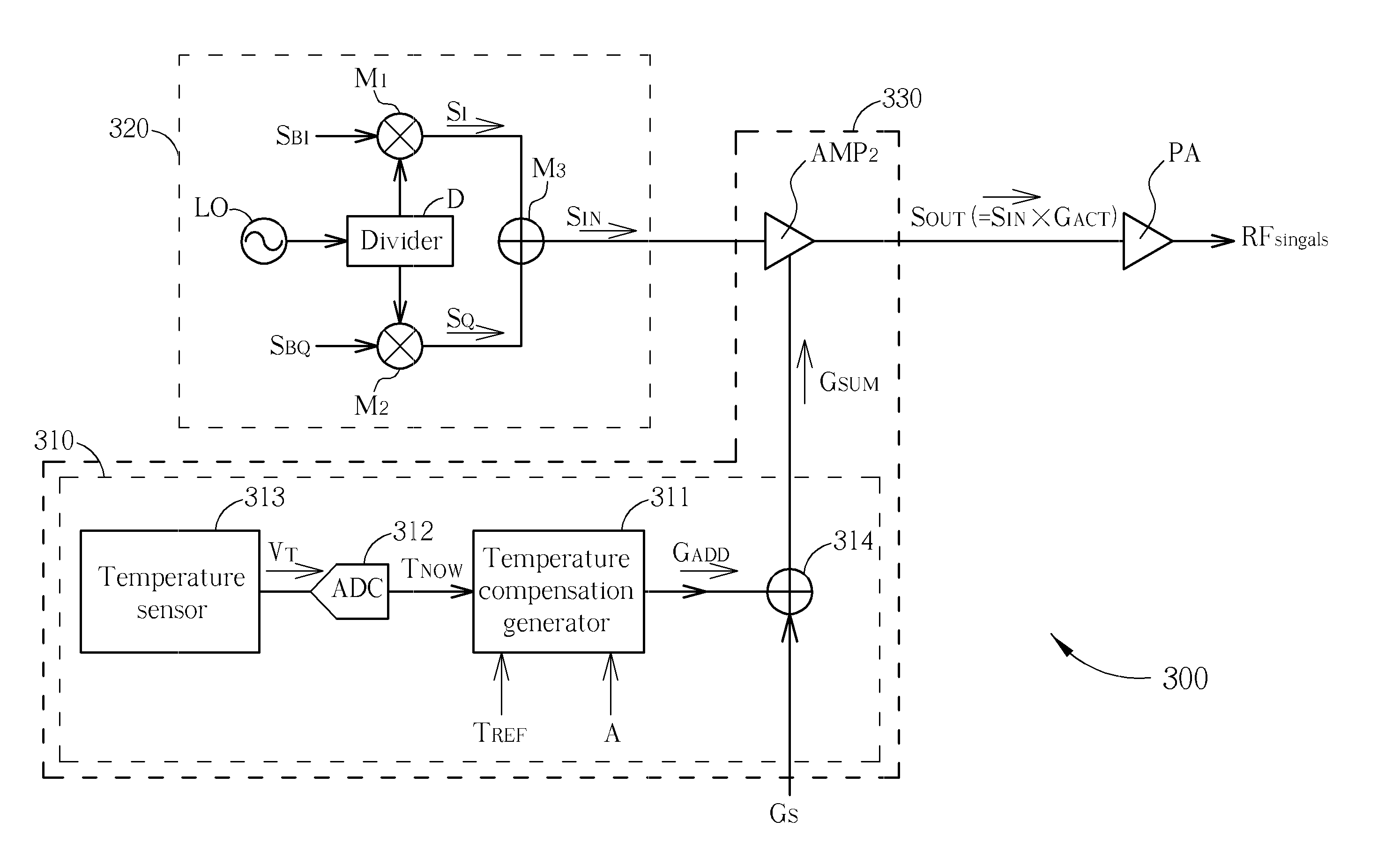
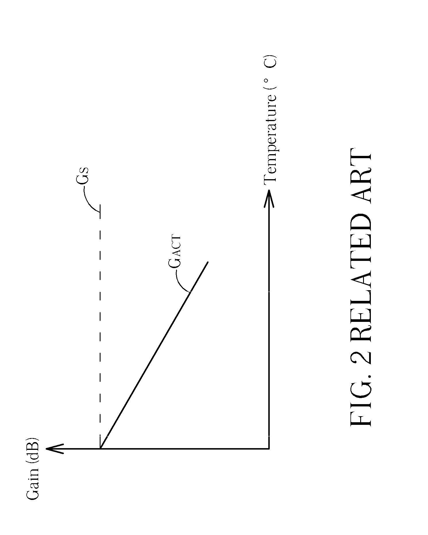
[0019]Please refer to FIG. 3 and FIG. 4. FIG. 3 is a diagram illustrating a radio frequency (RF) transmitter 300 of the present invention. FIG. 4 is a diagram illustrating the actual gain GACT of the amplifier AMP2 after the gain compensation device 310 is utilized. The RF transmitter 300 comprises a gain compensation device 310, a RF module 320, an amplifier AMP2, and a power amplifier PA. The power amplifier PA outputs RF signals according to the input signal SOUT. The gain compensation device 310 and the amplifier AMP2 form a temperature compensation amplifying module 330. The temperature compensation amplifying module 330 amplifies the received signals without temperature effect. In other words, in the temperature compensation amplifying module 330, the amplifier AMP2 utilizes the gain compensation device 310 to eliminate the temperature effect of RF transmitter 300 so as for the signals outputted from the temperature compensation amplifying module 330 are not affected by the va...


PUM


Abstract

A gain compensation device for adjusting gain of an amplifier over temperature is disclosed. The gain of the amplifier is controlled by signals on a gain control end of the amplifier. The gain compensation device comprises a temperature compensation generator, an adder, and a temperature sensor. The temperature compensation generator is for generating an additional gain parameter according to a reference temperature, a current temperature, and a temperature coefficient. The adder comprises a first input end, coupled to the temperature compensation generator for receiving the additional gain parameter, a second input end for receiving a default gain parameter, and an output end coupled to the gain control end of the amplifier for outputting sum of the additional gain parameter and the default gain parameter. The temperature sensor is for providing the current temperature.

Description

BACKGROUND OF THE INVENTION [0001]1. Field of the Invention[0002]The present invention relates to a gain compensation device over temperature, and more particularly, to a gain compensation device adjusting the gain of an amplifier according to the temperature.[0003]2. Description of the Prior Art[0004]Please refer to FIG. 1. FIG. 1 is a diagram illustrating conventional amplifier AMP1. The input end of the amplifier AMP1 receives an input signal SIN, and the output end of the amplifier AMP1 outputs an output signal SOUT. As shown in FIG. 1, the actual gain GACT of the amplifier AMP1 can be set according to the default gain parameter GS through the gain control end of the amplifier AMP1. Therefore, the input signal SIN can be amplified for generating the output signal SOUT, and the output signal SOUT reaches to the target power level under such setting, wherein the relation between the input signal SIN and the output signal SOUT can be described as in the following equation:SOUT=SIN×...

Claims


Application Information

Patent Timeline
IPC IPC(8): H04B1/04H03F1/00
CPCH03F3/189H03F3/24H03F2200/451H03F2200/447H03F2200/411
Inventor LEE, YI-BINTSENG, PO-SEN
Owner MEDIATEK INC
Why Eureka
Try Eureka