Method and System for a Sub-Harmonic Transmitter Utilizing a Leaky Wave Antenna

a leaky wave antenna and sub-harmonic technology, applied in the field of wireless communication, can solve the problems of power inefficiency of transmitters and/or receivers in comparison to other blocks of portable communication devices

Active Publication Date: 2010-12-09
AVAGO TECH INT SALES PTE LTD
View PDF99 Cites 41 Cited by
  • Summary
  • Abstract
  • Description
  • Claims
  • Application Information

AI Technical Summary

Benefits of technology

[0010]A system and / or method for a sub-harmonic transmitter utilizing a leaky wave antenna, substantially as shown in and / or described in connection with at least one of the figures, as set forth more completely in the claims.

Problems solved by technology

Additionally, transmit and / or receive circuitry within such mobile wireless devices often account for a significant portion of the power consumed within these devices.
Moreover, in some conventional communication systems, transmitters and / or receivers are often power inefficient in comparison to other blocks of the portable communication devices.

Method used


Image

  • Method and System for a Sub-Harmonic Transmitter Utilizing a Leaky Wave Antenna
  • Method and System for a Sub-Harmonic Transmitter Utilizing a Leaky Wave Antenna
  • Method and System for a Sub-Harmonic Transmitter Utilizing a Leaky Wave Antenna

Examples


Embodiment Construction

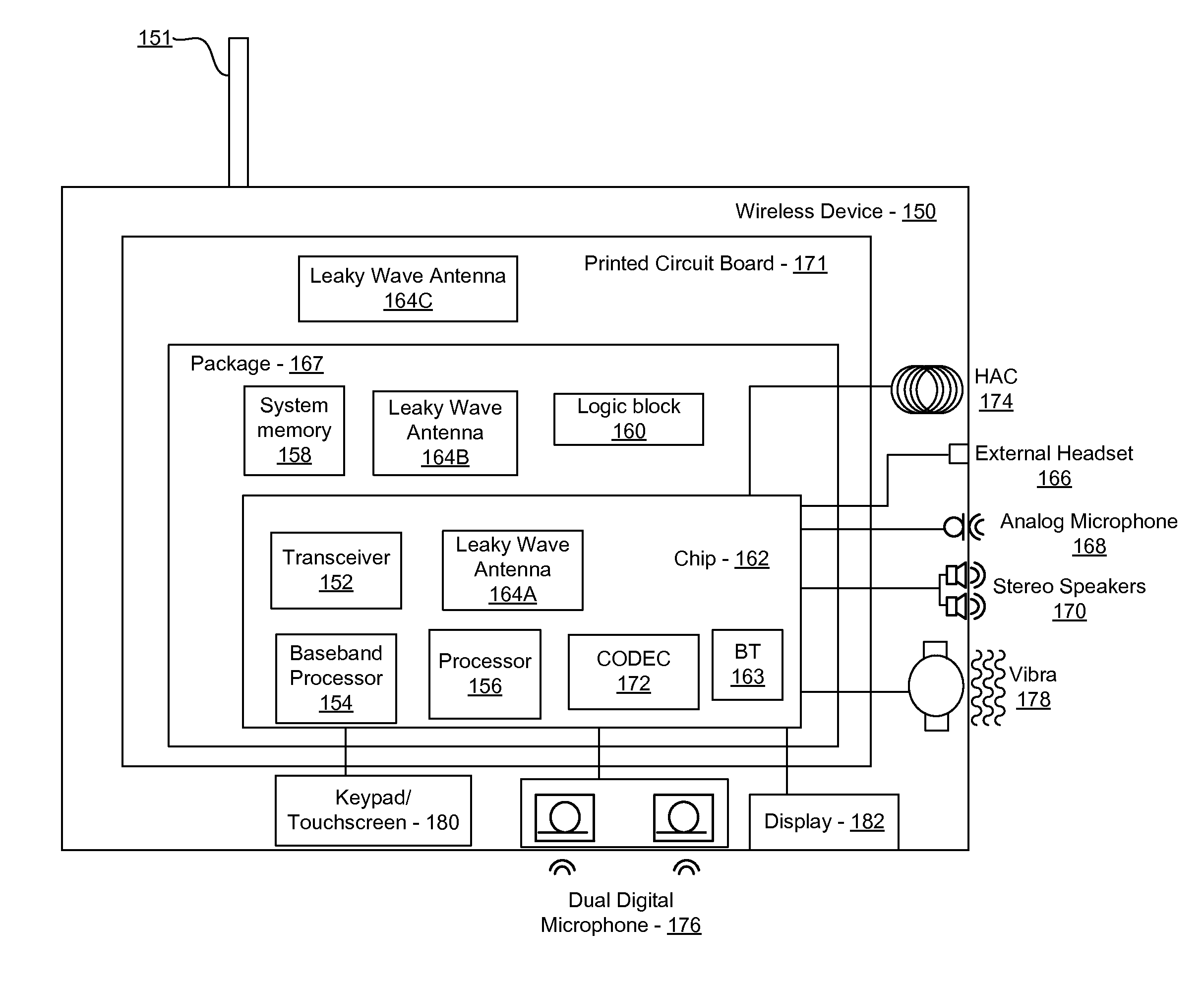
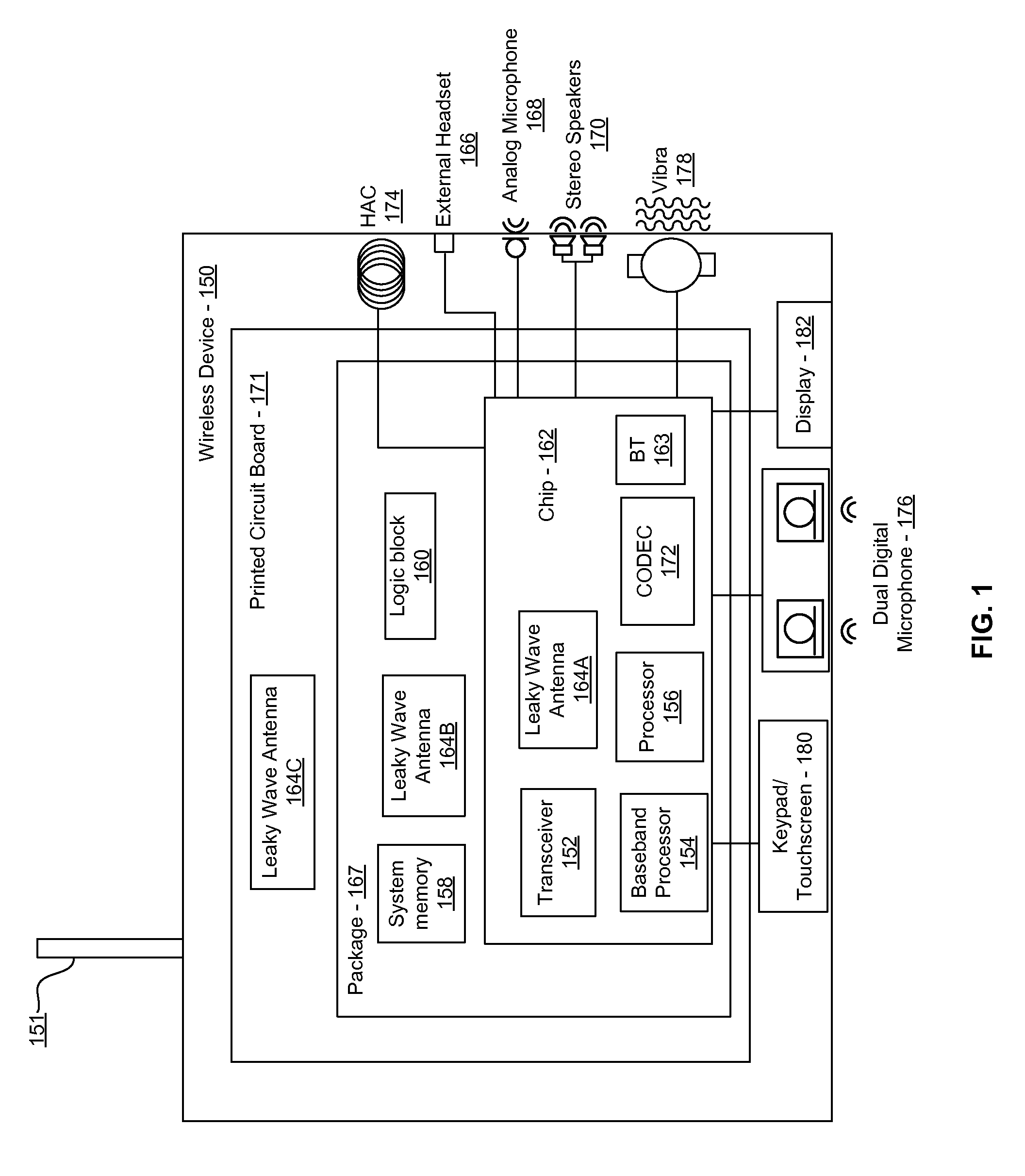
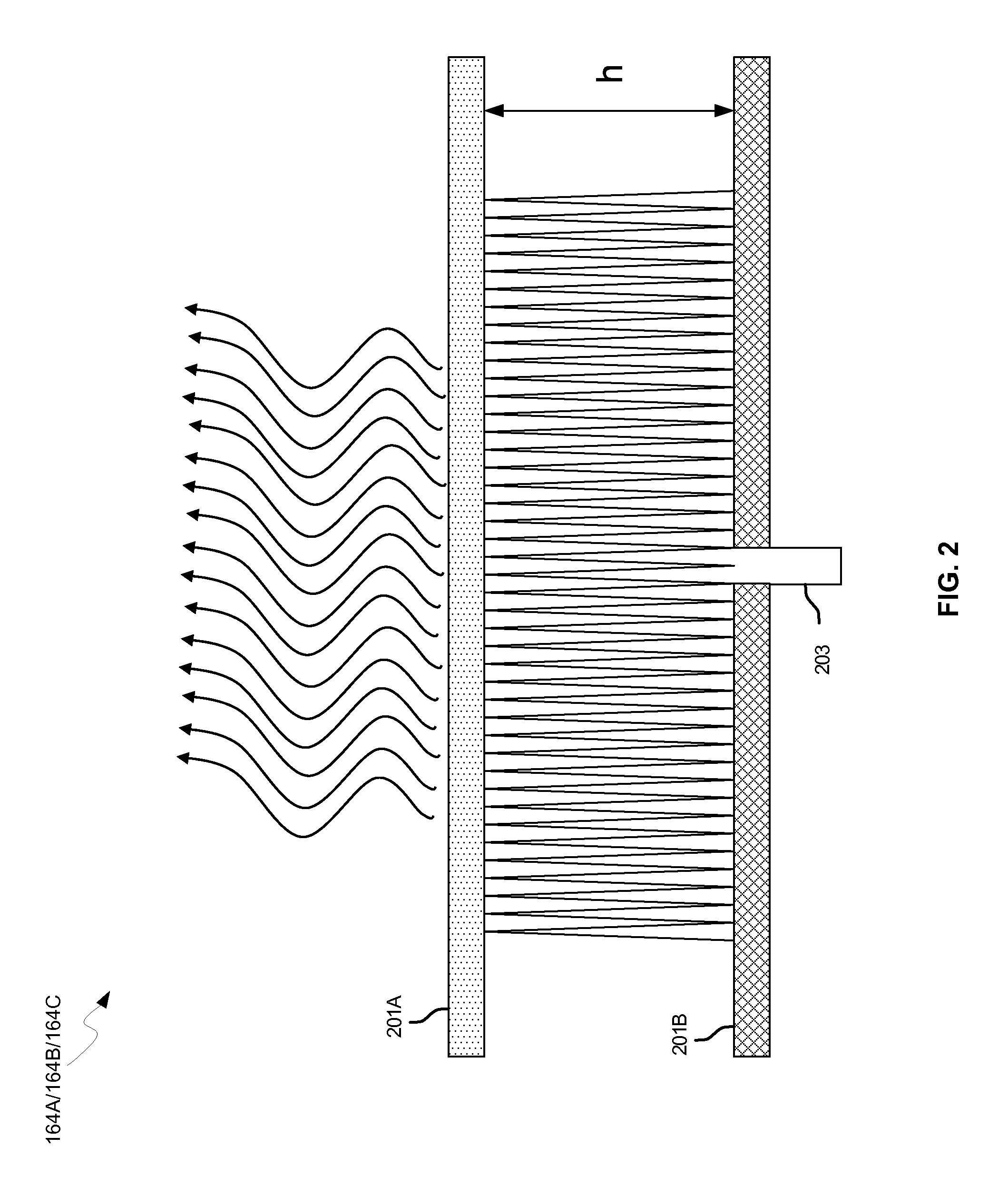
[0020]Certain aspects of the invention may be found in a method and system for a sub-harmonic transmitter utilizing a leaky wave antenna. Exemplary aspects of the invention may comprise transmitting wireless signals at a harmonic frequency of a source signal utilizing one or more leaky wave antennas in a wireless device comprising one or more transceivers on a chip. The one or more leaky wave antennas may be configured with a resonant frequency at the harmonic frequency. The source signal may be communicated to the one or more leaky wave antennas utilizing a power amplifier, which may be operated in a switching mode thereby generating a square wave from the source signal. The one or more leaky wave antennas may be integrated on the chip, on a package to which the chip is affixed and / or on a printed circuit board to which the chip is affixed. In accordance with an exemplary embodiment of the invention, the harmonic frequency may be three times a frequency of the source signal. The tr...


PUM


Abstract

Methods and systems for a sub-harmonic transmitter utilizing a leaky wave antenna are disclosed and may include transmitting wireless signals at a harmonic frequency of a source signal utilizing one or more leaky wave antennas (LWAs) in a wireless device including one or more transceivers on a chip. The LWAs may be configured with a resonant frequency at the harmonic frequency. The source signal may be communicated to the LWAs utilizing a power amplifier, which may be operated in switching mode thereby generating a square wave from the source signal. The LWAs may be integrated on the chip, on a package to which the chip is affixed and/or on a printed circuit board to which the chip is affixed. The harmonic frequency may be three times a frequency of the source signal. The transmitted wireless signal may be amplitude modulated utilizing a bias voltage applied to the LWAs.

Description

CROSS-REFERENCE TO RELATED APPLICATIONS / INCORPORATION BY REFERENCE[0001]This application makes reference to and claims priority to U.S. Provisional Application Ser. No. 61 / 246,618 filed on Sep. 29, 2009, and U.S. Provisional Application Ser. No. 61 / 185,245 filed on Jun. 9, 2009.[0002]This application also makes reference to:U.S. patent application Ser. No. ______ (Attorney Docket No. 21181US02) filed on even date herewith;U.S. patent application Ser. No. ______ (Attorney Docket No. 21205US02) filed on even date herewith;U.S. patent application Ser. No. ______ (Attorney Docket No. 21211US02) filed on even date herewith;U.S. patent application Ser. No. ______ (Attorney Docket No. 21214US02) filed on even date herewith;U.S. patent application Ser. No. ______ (Attorney Docket No. 21227US02) filed on even date herewith;U.S. patent application Ser. No. ______ (Attorney Docket No. 21231US02) filed on even date herewith;U.S. patent application Ser. No. ______ (Attorney Docket No. 21232US02)...

Claims


Application Information

Patent Timeline
Patent Type & Authority Applications(United States)
IPC IPC(8): H04B1/04
CPCH01Q1/2283H01Q13/22H04B5/0031H01Q15/006G01S13/06H01Q13/20H04B1/04H04B7/24H04B1/0458H01L2224/16225H01L2224/32225H01L2224/73204H01L2924/13091H01L2924/00G06K7/10316H01Q15/0066H01Q15/23H01Q19/06
Inventor ROFOUGARAN, AHMADREZAROFOUGARAN, MARYAM
Owner AVAGO TECH INT SALES PTE LTD
Why Eureka
Try Eureka