Bone screw system and method for the fixation of bone fractures

a bone screw and fixation method technology, applied in the field of bone screw systems and methods for the fixation of fractures, can solve the problems of limited shaft extension, difficult for operators to determine how far the shaft should be extended, and not readily securable, so as to reduce the fracture and load the compressive mechanism

Inactive Publication Date: 2010-12-09
ORTHOIP
View PDF99 Cites 100 Cited by
  • Summary
  • Abstract
  • Description
  • Claims
  • Application Information

AI Technical Summary

Benefits of technology

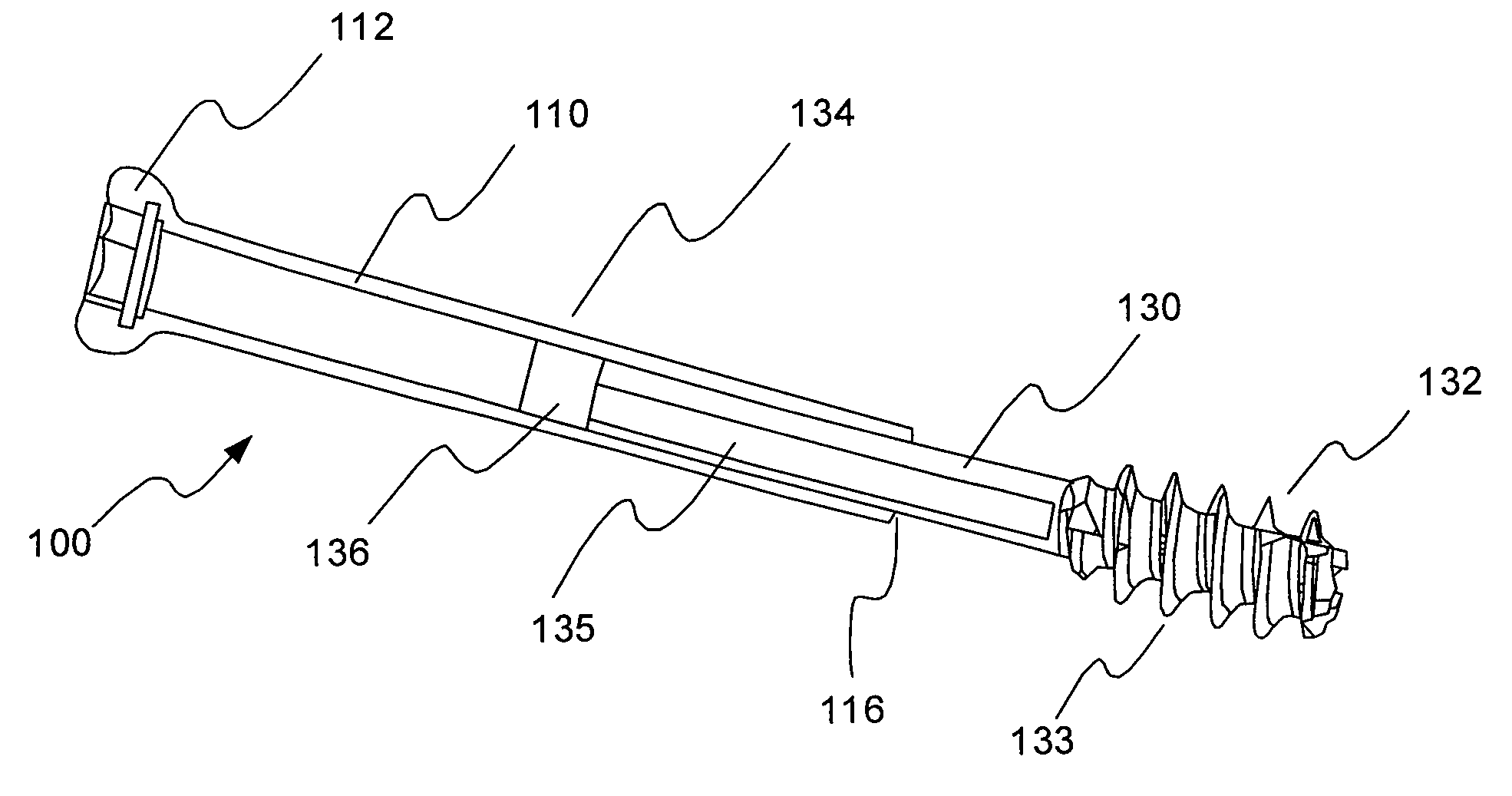
[0007]The system generally includes extendable bone screws with compressive elements which facilitate the stabilization and fixation of bone fractures. In an exemplary embodiment, the shaft of the bone screw device may be configured to be fully or partially extended relative to the sleeve of the bone screw device, after being driven into the bone.
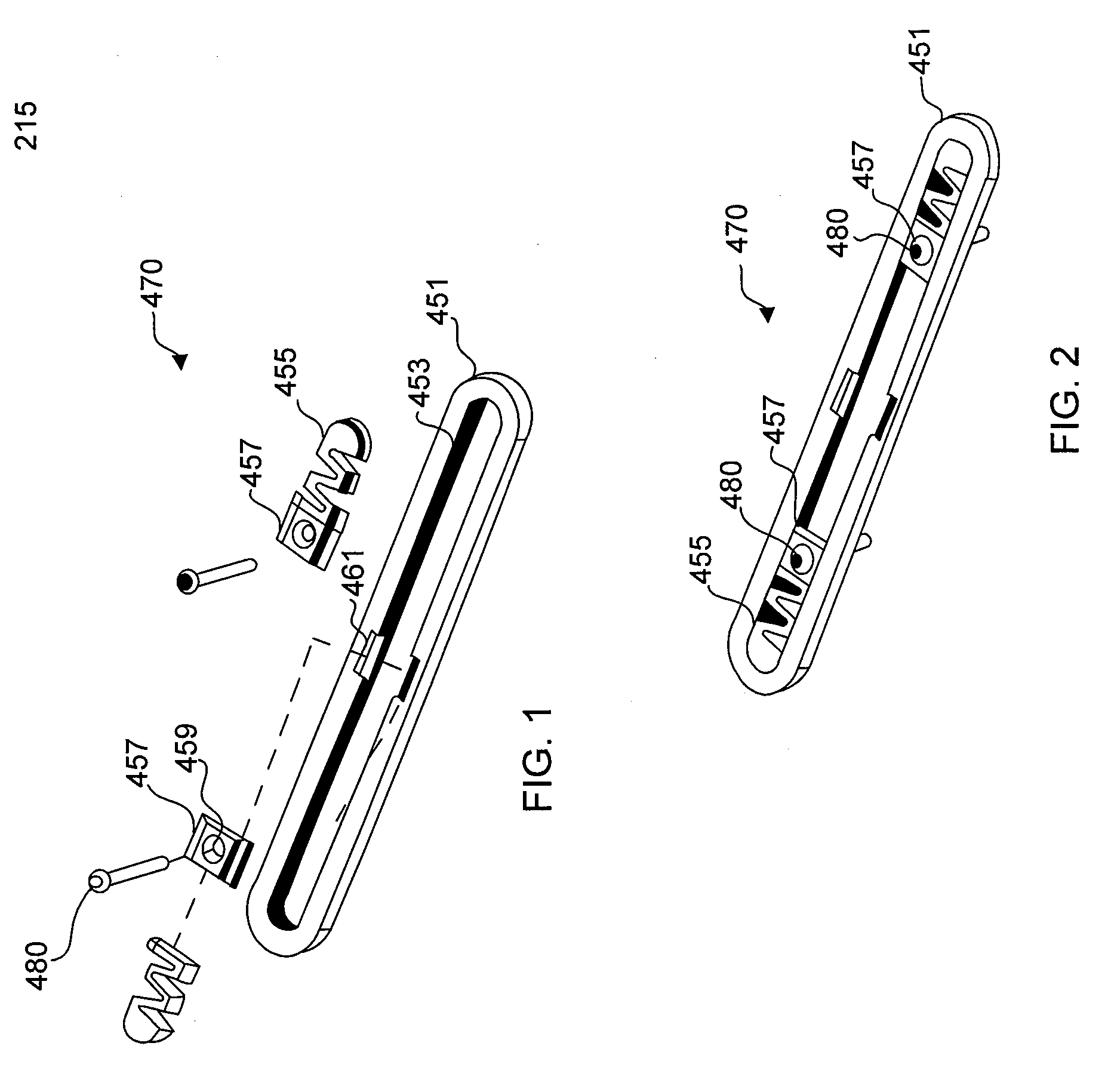
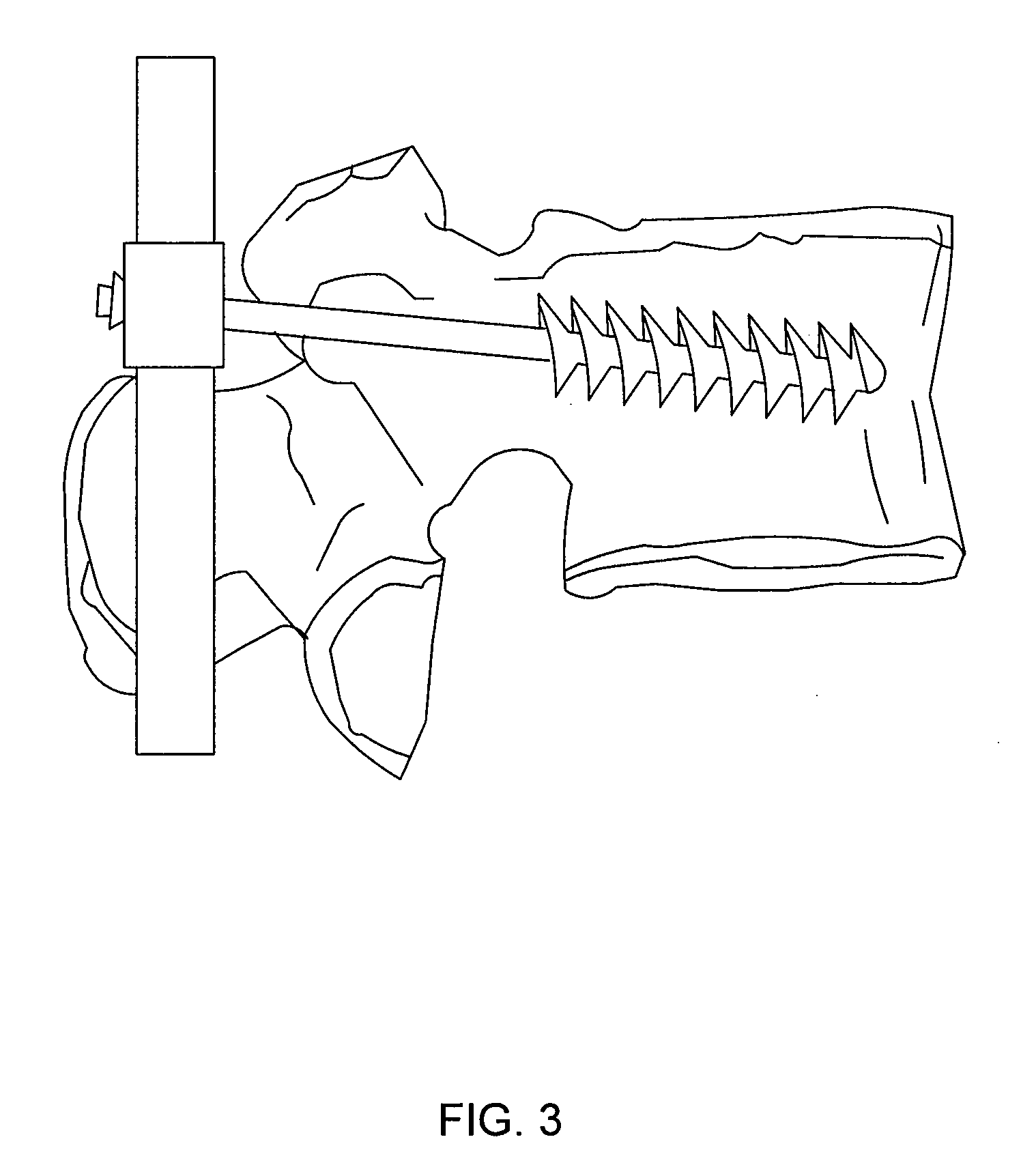
[0008]In various embodiments, an extendable bone screw with a compressive element comprises blade threads on the distal end. The blade thread may be advanced into the bone and through an intramedullary rod by tapping the screw in the desired direction. The extendable bone screw with a compressive element may be implanted into a bone with the screw compressed. After the blade thread is secured within the bone, the sleeve may be pulled back, reducing the fracture and loading the compressive mechanism. The extendable bone screw with a compressive element may be secured in an extended position by interaction with the intramedullary rod.

Problems solved by technology

For example, the shafts of conventional bone screws are generally not extendable relative to the sleeves until the screw reaches the bone, making it difficult for operators to ascertain how far the shaft should be extended.
Moreover, when conventional bone screws are used in connection with locking plates, only limited extension of the shaft can occur before the threads of the locking plate secure with the threads of the bone screw and prevent further extension (e.g., 1 to 2 rotations).
Another disadvantage of conventional bone screws is that they are not readily securable relative to the bone stabilization devices at a specific angle of entry, and thus permit movement of the bone screw relative to the stabilization device.

Method used


Image

  • Bone screw system and method for the fixation of bone fractures
  • Bone screw system and method for the fixation of bone fractures
  • Bone screw system and method for the fixation of bone fractures

Examples


Embodiment Construction

[0035]The present invention is described herein and includes various exemplary embodiments in sufficient detail to enable those skilled in the art to practice the invention, and it should be understood that other embodiments may be realized without departing from the spirit and scope of the invention. Thus, the following detailed description is presented for purposes of illustration only, and not of limitation, and the scope of the invention is defined solely by the appended claims. The particular implementations shown and described herein are illustrative of the invention and its best mode and are not intended to otherwise limit the scope of the present invention in any way.

[0036]In general, the present invention facilitates the change in distance between objects, object portions, or surfaces, compresses objects or object portions together, and / or provides a configurable or random amount of pressure between surfaces. The system may facilitate changing, maintaining, reducing and / or ...


PUM


Abstract

An bone screw with comprising a sleeve, a shaft reciprocally received within the sleeve, and a compressive device is disclosed. The bone screw may be extended, placing a fracture in tension, after insertion into a bone and then retained in place by a setscrew that is retained by an intramedullary rod. The shaft of the bone screw may have a blade thread that allows the bone screw to be installed into a bone by tapping the bone screw with a hammer.

Description

CROSS-REFERENCE TO RELATED APPLICATIONS[0001]This application is a continuation-in-part of, and claims priority to, U.S. Ser. No. 12 / 769,529 filed Apr. 28, 2010 and entitled “BONE SCREW SYSTEM AND METHOD FOR THE FIXATION OF BONE FRACTURES.” The '529 application is a continuation-in-part of and claims priority to U.S. Ser. No. 12 / 425,225 filed Apr. 16, 2009 and entitled “BONE SCREW SYSTEM AND METHOD FOR THE FIXATION OF BONE FRACTURES.” The '225 application is a continuation-in-part of and claims priority to U.S. Ser. No. 12 / 369,589 filed Feb. 11, 2009 and entitled “STABILIZATION SYSTEM AND METHOD FOR THE FIXATION OF BONE FRACTURES.” The '589 application is a continuation-in-part of and claims priority to U.S. Ser. No. 12 / 258,013 filed Oct. 24, 2008 and entitled “BONE SCREW SYSTEM AND METHOD.” The '013 application is a continuation-in-part of and claims priority to U.S. Ser. No. 12 / 104,658 filed Apr. 17, 2008 and entitled “ADJUSTABLE BONE PLATE FIXATION SYSTEM AND METHOD.” The '658 ap...

Claims


Application Information

Patent Timeline
Patent Type & Authority Applications(United States)
IPC IPC(8): A61B17/58A61B17/86
CPCA61B17/7053A61B17/742A61B17/744A61B17/746A61B17/8004A61B17/8047A61B17/8057A61B17/8605A61B17/8625A61B17/8685A61B17/8863A61B17/8869A61B17/8875
Inventor TIPIRNENI, KISHOREVASSELLO, WAYNE
Owner ORTHOIP
Why Eureka
Try Eureka