
Inspection apparatus for tubular members

a tubular member and inspection apparatus technology, applied in the field of inspection apparatus, can solve the problems of pipelines being subject to often harsh environmental conditions, pipelines to weaken, and cracks along weld seams

Inactive Publication Date: 2010-12-16
CAIN JR JAMES M
View PDF7 Cites 21 Cited by
  • Summary
  • Abstract
  • Description
  • Claims
  • Application Information

AI Technical Summary

Benefits of technology

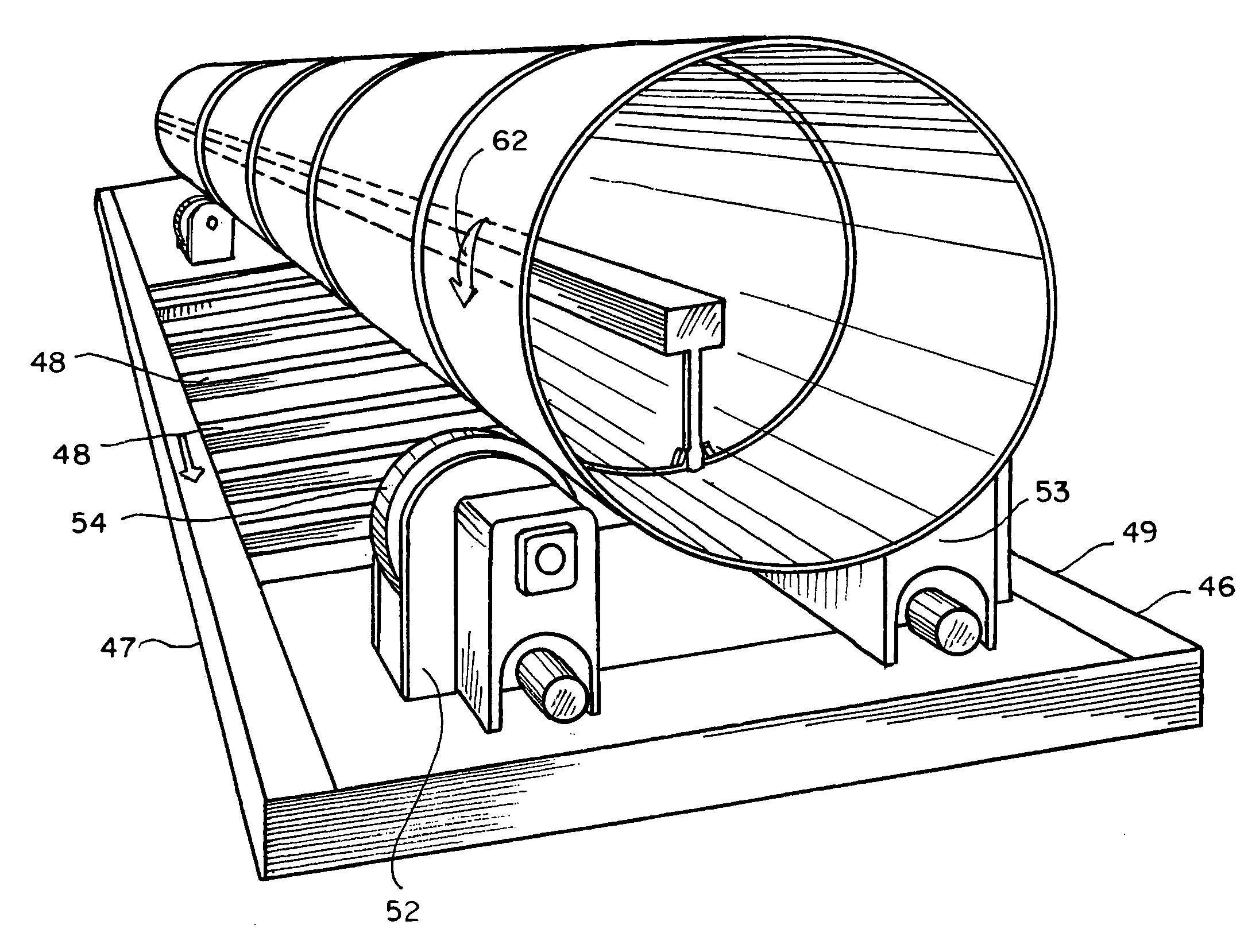
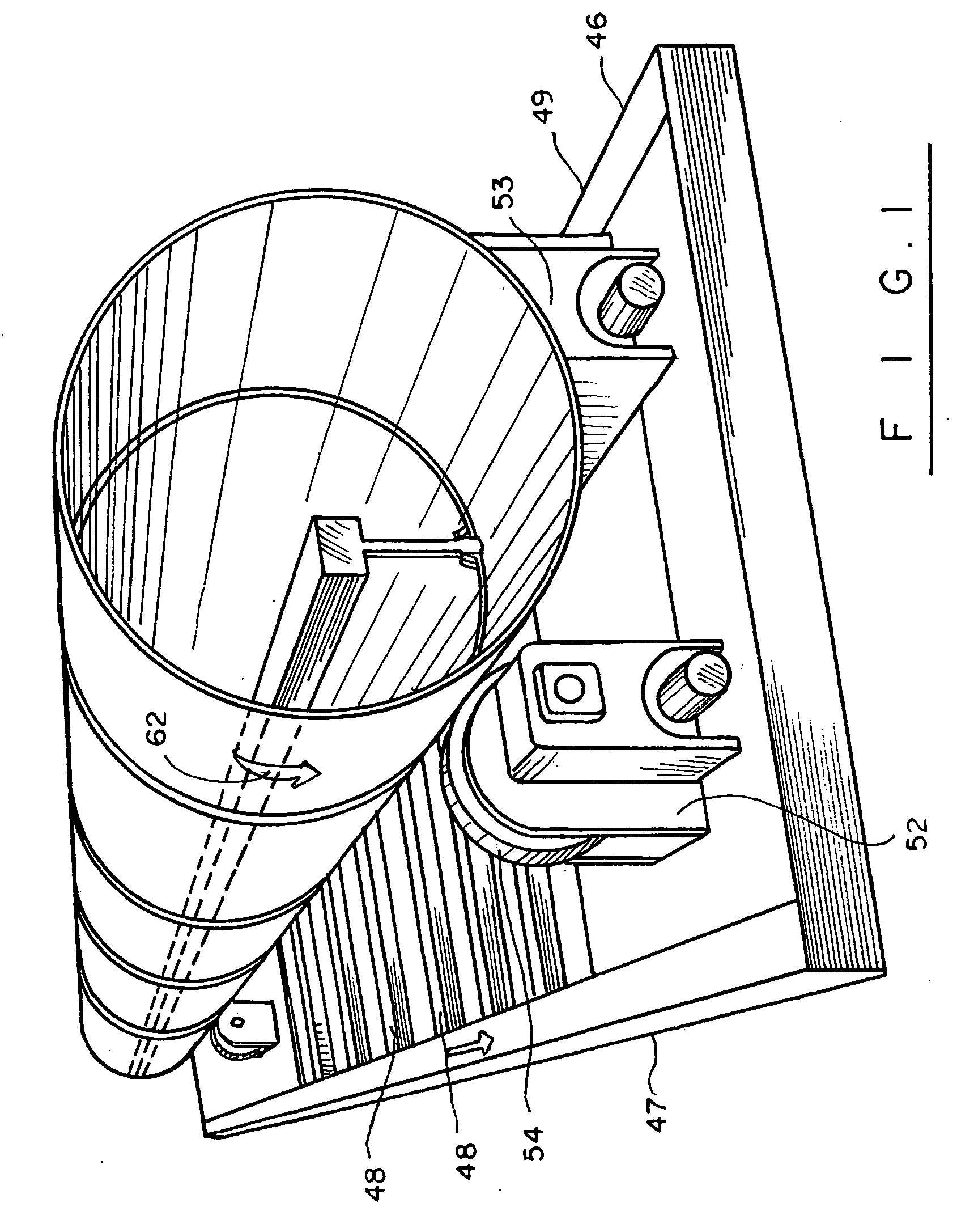
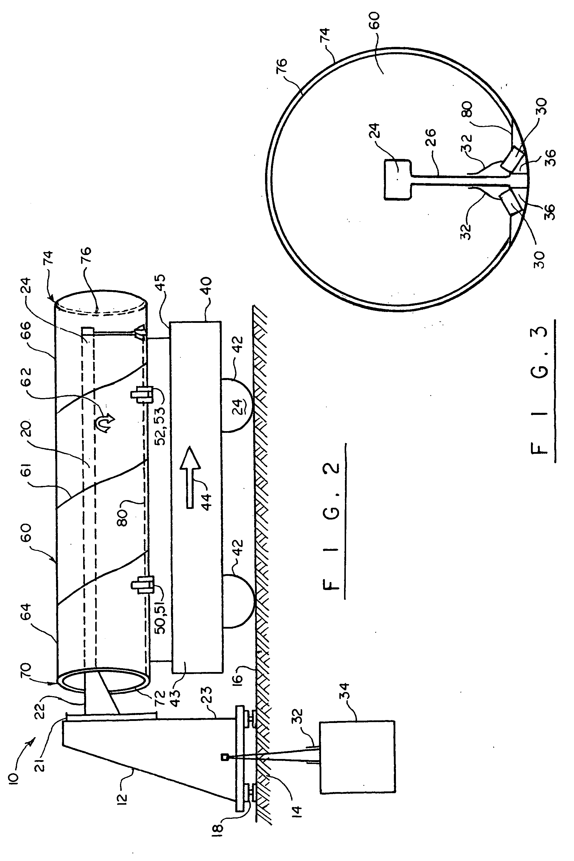
[0010]These and other objects of the invention are achieved through a provision of an ultrasonic inspection system useful for inspecting a tubular member provides for the use of ultrasonic transducer assembly for detecting weld flaws or other out-of range conditions in the tubular member. According to the invention, the tubular member is positioned horizontally on a rolling carriage and a predetermined amount of sound-conductive fluid is deposited into the tubular member. Wide rings secured to opposing open ends of the tubular member prevent the liquid from escaping, while forming a barrier for retaining a given level of liquid inside the tubular member. The transducers are submerged in the liquid and transmit / receive ultrasonic signals from reflected medium inside the tubular member. The transducers are connected to a computing control unit, which receives signals generated by the transducers and creates a report of any out-of range condition.

Problems solved by technology

Pipelines are installed underground and underwater, which results in the pipelines being subject to often harsh environmental conditions including temperature variations, deep sea pressures, and the like.
With time, the environment causes pipelines to weaken, sometimes crack along the weld seams, often times corrode.
Should the pipeline integrity become compromised, the material traveling along the pipeline may escape and cause substantial damage to the environment.
However, visible inspection has its limitations particularly inspection of the inner surface weld may become inefficient and expensive.
However, this method relies largely on the experience of the technician performing the test.
Human error can affect the results of the test, leading to missed imperfections in the weld.

Method used


Image

  • Inspection apparatus for tubular members
  • Inspection apparatus for tubular members
  • Inspection apparatus for tubular members

Examples


Embodiment Construction

[0015]Turning now to the drawings in more detail, numeral 10 designates the pipe testing apparatus of the present invention. The apparatus 10 comprises an upright pedestal 12 positioned on the ground 14 at or near railway tracks 16. The pedestal 12 can be elevated using the legs 18 for alignment with a tubular member being tested and positioned on a carriage. An elongated beam 20 is secured at a proximate end 22 thereof to the pedestal 12. The beam 20 is cantilevered from the pedestal 12 and extends transversely to an attachment plate 21 secured to a front surface 23 of the pedestal 12. The length of the beam 20 is selected to approximate the length of a tubular member 30 being inspected. A supporting bracket 26 is secured to a distant end 24 of the beam 20. The bracket 26 extends downwardly from the beam 20, supporting the array of ultrasonic transducers 30 by a free end thereof.

[0016]A carriage assembly 40 for laterally supporting a tubular member is mounted on rotating wheels 42....


PUM


Abstract

An ultrasonic inspection system useful for inspecting a tubular member provides for the use of ultrasonic transducer assembly for detecting weld flaws or other out-of range conditions in the tubular member. According to the invention, the tubular member is positioned horizontally on a rolling carriage and a predetermined amount of sound-conductive fluid is deposited into the tubular member. Wide rings secured to opposing open ends of the tubular member prevent the liquid from escaping, while forming a barrier for retaining a given level of liquid inside the tubular member. The transducers are submerged in the liquid and transmit / receive sonic booms from reflected medium inside the tubular member. The transducers are connected to a computing control unit, which receives signals generated by the transducers and creates a report of any out-of range condition.

Description

BACKGROUND OF THE INVENTION[0001]The present invention relates to an inspection apparatus, and more particularly, to an inspection apparatus suitable for inspecting tubular members, such as pipes.[0002]Pipelines of various lengths and sizes are widely used in a variety of industries, transporting oil, gas, particulate matter, small solids suspended in fluids and other materials. Pipelines are installed underground and underwater, which results in the pipelines being subject to often harsh environmental conditions including temperature variations, deep sea pressures, and the like. With time, the environment causes pipelines to weaken, sometimes crack along the weld seams, often times corrode. Should the pipeline integrity become compromised, the material traveling along the pipeline may escape and cause substantial damage to the environment.[0003]As a consequence, considerable efforts are dedicated to the inspection of the pipes during manufacturing process. Visual inspection may ser...

Claims


Application Information

Patent Timeline
IPC IPC(8): G01N29/04
CPCG01N29/07G01N29/225G01N29/265G01N29/28G01N2291/106G01N2291/2636G01N2291/2675
Inventor CAIN, JR., JAMES M.
Owner CAIN JR JAMES M
Learn More