Valve timing control apparatus

Active Publication Date: 2010-12-16
DENSO CORP
View PDF4 Cites 49 Cited by
  • Summary
  • Abstract
  • Description
  • Claims
  • Application Information

AI Technical Summary

Benefits of technology

[0007]In view of the foregoing and other problems, it is an object of the present invention to produce a valve timing control apparatus configured to perform a rotation phase control and a phase lock control by using a single element of a single control valve and capable of enhancing a phase lock performance in a regulation phase. According to one aspect of the present invention, a valve timing control apparatus for controlling a valve timing of a valve configured to be opened and closed by a camshaft in accordance with a torque transmitted from a crankshaft of an internal combustion engine, the valve timing control apparatus configured to control the valve timing by utilizing a hydraulic fluid supplied from a supply source with a driving operation of the internal combustion engine, the valve timing control apparatus comprises a housing rotatable with the crankshaft, the housing having a recess dented from an inner surface of the housing. The valve timing control apparatus further comprises a vane rotor rotatable with the camshaft, the vane rotor having a vane partitioning an interior of the housing into an advance chamber and a retard chamber in a rotative direction, the vane rotor configured to change a rotation phase relative to the housing to an advance side or a retard side correspondingly when a hydraulic fluid is supplied into the advance chamber or the retard chamber. The valve timing control apparatus further comprises a lock unit having a lock chamber, the lock unit configured to lock the vane rotor relative to the housing when a hydraulic fluid is discharged from the lock chamber, the lock unit configured to release the lock when a hydraulic fluid is supplied into the lock chamber. The valve timing control apparatus further comprises a valve body having an operation port, which is communicable with the advance chamber and the retard chamber, a lock port, which is communicable with the lock chamber, a supply port, which is configured to be supplied with a hydraulic fluid from the supply source, and an exhaust port configured to discharge a hydraulic fluid. The valve timing control apparatus further comprises a valve element linearly movable in opposite

Problems solved by technology

Accordingly, a large space is needed for accommodating the two control valves.
In addition, a large amount of electricity may be consumed to drive the two control valves.
In such a condition, when

Method used


Image

  • Valve timing control apparatus
  • Valve timing control apparatus
  • Valve timing control apparatus

Examples


embodiments

[0028]As follows, embodiments will be described with reference to drawings. In the embodiments, an element described in a subsequent embodiment may be denoted with the same reference numeral, and description of such an element may be omitted. When only a part of a structure of an element is described in an embodiment, other part of the structure of the element may be equivalent to that of another foregoing embodiment. Combinations of elements are not limited to those specified in an embodiment. As long as a combination does not cause a defect, any combinations of elements and embodiments may be made.

first embodiment

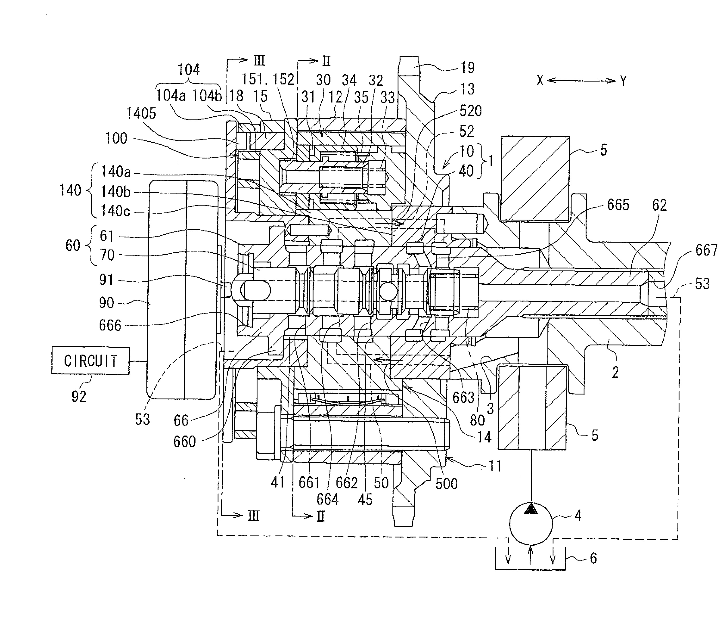
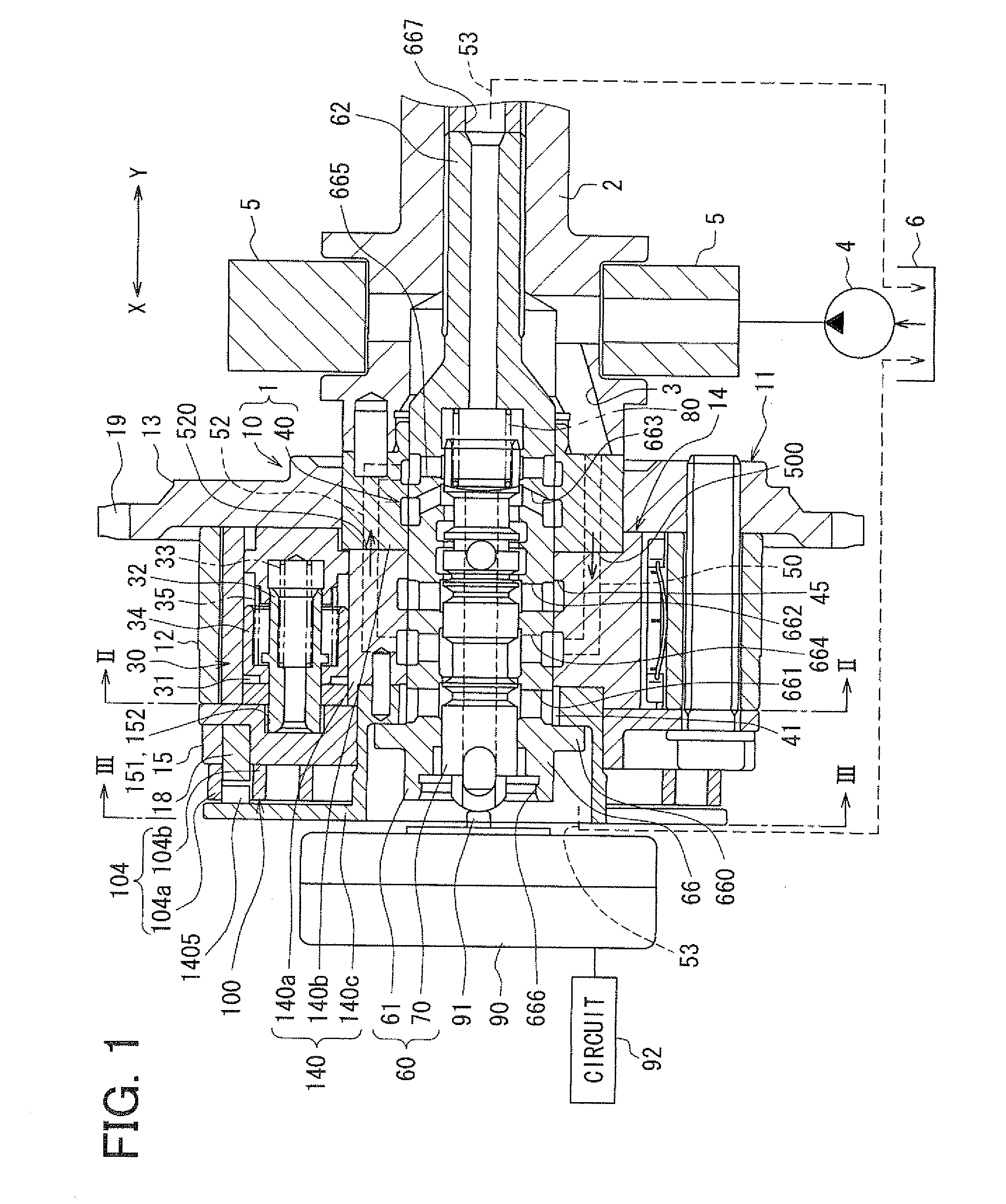
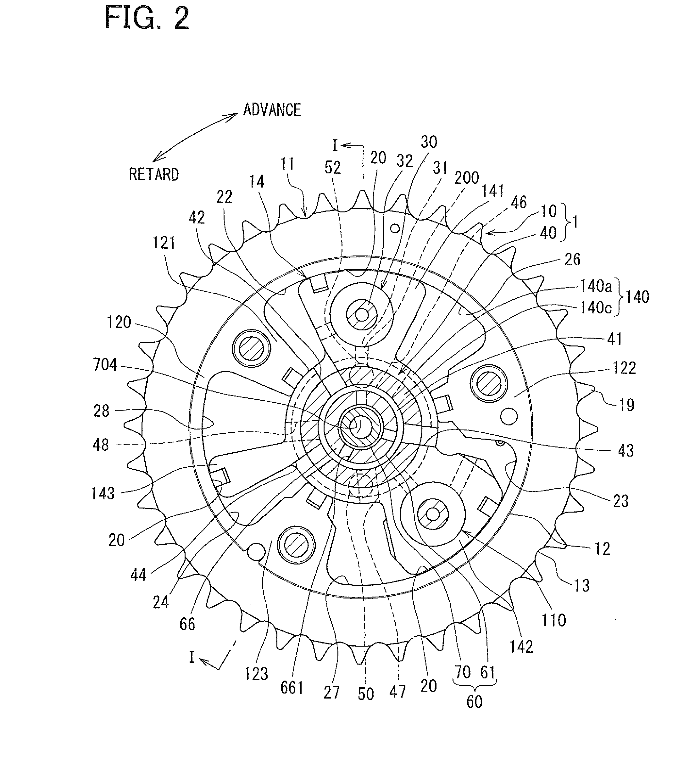
[0029]FIG. 1 shows an example in which a valve timing control apparatus 1 according to a first embodiment is applied to an internal combustion engine of a vehicle. FIG. 1 is a view taken along the line I-I in FIG. 2. The valve timing control apparatus 1 controls a valve timing of an intake valve, which functions as a valve train opened and closed by a camshaft 2, by using a working fluid. The valve timing control apparatus 1 includes an actuator portion 10 and a control portion 40.

[0030]The actuator portion 10 is provided to a transmission system, which transmits engine torque from a crankshaft ((not shown)) to the camshaft 2, and driven by the working fluid. The control portion 40 controls supply of the working fluid to the actuator portion 10.

[0031](Actuator Portion)

[0032]First, the actuator portion 10 will be described in detail. In the actuator portion 10 shown in FIGS. 1, 2, a housing 11 is configured of a shoe housing 12, a sprocket 13, a front plate 15, and the like. The meta...

second embodiment

[0154]The second embodiment as a modification of the first embodiment will be described with reference to FIGS. 12 and 13. As shown in FIG. 12, the present second embodiment is different from the first embodiment in the following two structures. First, contrary to the phase lock portion 30 of the first embodiment, a phase lock portion 30A of the second embodiment is a first regulating member 32A, which is a single pin. Second, the advance communication passage 201 and the retard communication passage 202 are not provided.

[0155](First Regulating and Locking Structure)

[0156]The first accommodation hole 310 of the second embodiment accommodates a first metallic regulating member 32A and a first resilient member 33A. The first resilient member 33A includes a metallic compression coil spring to generate resilience when being elastic deformed to bias the first regulating member 32A toward the front plate 15. The lock chamber 31 is an annular space formed between the inner surface of the f...


PUM


Abstract

A vane rotor includes a vane to partition an advance chamber from a retard chamber. A valve element communicates a lock port with an exhaust port to drain a fluid from the lock port when moving in a first region including an end of a movable range in the first direction. The regulating member moves in the vane rotor in a thrust direction into a recess dented from an inner surface of the housing by being biased from a resilient member to lock the rotation phase in a regulation phase in the first region when a fluid is drained from the lock chamber. The valve element is configured to communicate an operation port with a supply port to supply a fluid into the advance chamber when being in a throttle region in the first region such that a flow of a fluid supplied to the advance chamber is throttled to be less than a flow of a fluid when the valve element is in the end of the movable range in the first direction.

Description

CROSS REFERENCE TO RELATED APPLICATIONS[0001]This application is based on and incorporates herein by reference Japanese Patent Application No. 2009-139425 filed on Jun. 10, 2009.FIELD OF THE INVENTION[0002]The present invention relates to a valve timing control apparatus for controlling a valve timing of a valve, which is opened and dosed by a camshaft according to a torque transmitted from a crankshaft in an internal combustion engine, by utilizing a hydraulic fluid supplied from a supply source with a driving operation of the internal combustion engine.BACKGROUND OF THE INVENTION[0003]Conventionally, a known valve timing control apparatus includes a housing, which is rotatable with rotation of a crankshaft and a vane rotor, which is rotatable with rotation of a camshaft and having a vane to partition an operation chamber in the housing in a rotative direction. Such a valve timing control apparatus is configured to change a rotation phase of the vane rotor relative to the housing b...

Claims


Application Information

Patent Timeline
IPC IPC(8): F01L1/344
CPCF01L1/3442F01L2001/0476F01L2001/34473F01L2001/3443
Inventor YAMAGUCHI, TAKASHITAKENAKA, AKIHIKO
Owner DENSO CORP
Why Eureka
Try Eureka