Platform technology for industrial separations

a technology for industrial separation and platforms, applied in separation processes, membranes, water/sewage multi-stage treatment, etc., can solve the problems of large device/system footprint, slow process time, and high energy requirements

Inactive Publication Date: 2010-12-16
PALO ALTO RES CENT INC
View PDF37 Cites 45 Cited by
  • Summary
  • Abstract
  • Description
  • Claims
  • Application Information

AI Technical Summary

Problems solved by technology

All, however, suffer from one or more of the following issues: high energy requirements, large footprint of the device / system, slow process times, low throughput, batch processing, and implementation / infrastructure complexity.
The micro-scale methods require especially high energy to throughput ratio and precise control over the separation mechanism(s) and work only for low mass loading.

Method used


Image

  • Platform technology for industrial separations
  • Platform technology for industrial separations
  • Platform technology for industrial separations

Examples


Embodiment Construction

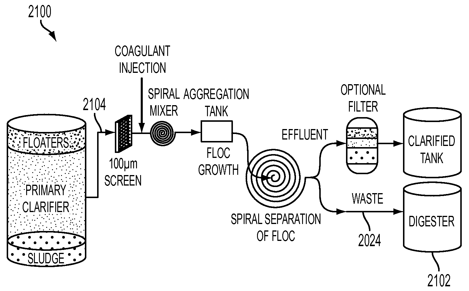
[0027]The following discussion describes enhanced features of a spiral mixer to include aggregate conditioning capabilities; and provides process schematics for applications of this spiral mixer-conditioner where this platform technology is applicable.

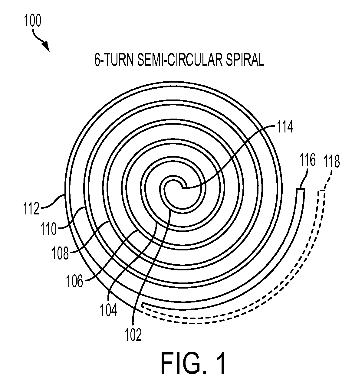
[0028]Spiral mixers previously disclosed in the material incorporated herein by reference allow for turbulent mixing of a chemical injected into a flow stream just ahead of a 90 degree turn at the mixer inlet and throughout the spiral channels of the mixer. In the spiral mixer-conditioner 100 of FIG. 1, aggregate conditioning capabilities are added to that mixer.

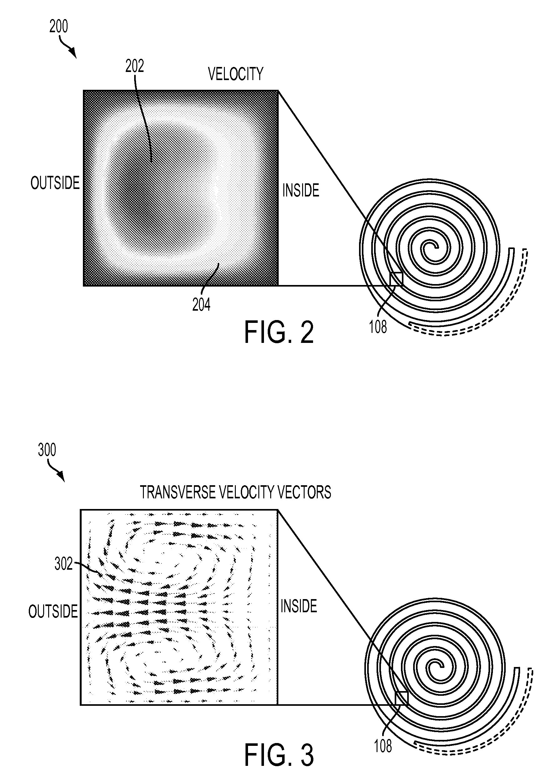
[0029]In the embodiment of FIG. 1, mixing takes place in the first two turns 102, 104 of spiral mixer-conditioner 100 where the fluid stream regime is designed for high Dean number (i.e., at or above the critical number of 150) operation. In this regime, transverse fluid flows within the channels cannot reach a force equilibrium so particle (particulate) suspensions continue a ...


PUM

PropertyMeasurementUnit
diameteraaaaaaaaaa
sizeaaaaaaaaaa
aggregate sizeaaaaaaaaaa

Abstract

A method and system for treating a fluid stream includes inputting a fluid stream to an input section of the fluid treatment system and receiving the fluid stream via spiral mixer-conditioner. The spiral mixer-conditioner mixes and conditions the input stream. Thereafter the mixed and conditioned fluid stream is input to a spiral separator where the mixed and conditioned fluid stream is separated into at least two fluid streams, a first fluid stream having particulates in the input stream removed, and the second fluid stream having the particulates in the input fluid stream concentrated.

Description

CROSS REFERENCE TO RELATED PATENTS AND APPLICATIONS[0001]Cross Reference is hereby made to related patent applications, U.S. patent application Ser. No. [Atty. Dkt. No. 20081938-US-NP], filed [Unknown], by Lean et al., entitled, “Spiral Mixer for Floc Conditioning”; U.S. patent application Ser. No. [20081254-US-NP], filed [Unknown], by Lean et al., entitled, “Stand-Alone Integrated Water Treatment System For Distributed Water Supply To Small Communities”; and U.S. patent application Ser. No. [Atty. Dkt. No. 20080169-US-NP], filed [Unknown], by Lean et al., entitled, “Method and Apparatus For Continuous Flow Membrane-Less Algae Dewatering”, the specifications of which are each incorporated by reference herein in their entirety.BACKGROUND[0002]Conventional macro-scale separation methods include floatation, sedimentation, centrifugation, and filtration. More recent developments in microfluidics include the use of micro-scale multi-physics forces for separation and enrichment. All, howe...

Claims


Application Information

Patent Timeline
Patent Type & Authority Applications(United States)
IPC IPC(8): B01D21/00C02F1/00C02F1/52B01F5/00
CPCB01D21/01B01D21/26B01D2311/04C02F1/001C02F1/52C02F9/00C02F2001/007C02F2301/026B01D61/04B01F13/0059B01F5/0647B01D61/025B01D21/265B01D2311/2676B01D2311/12B01F25/4331B01F33/30
Inventor LEAN, MENG H.CHANG, NORINE E.KOLE, ASHUTOSHSEO, JEONGGI
Owner PALO ALTO RES CENT INC
Why Eureka
Try Eureka