Light-emitting unit adapter module

Inactive Publication Date: 2010-12-16
KWO GER METAL TECH
View PDF6 Cites 17 Cited by
  • Summary
  • Abstract
  • Description
  • Claims
  • Application Information

AI Technical Summary

Benefits of technology

[0011]The present invention has been accomplished under the circumstances in view. It is therefore the main object of the present invention to provide a light-emitting unit adapter module, which dissipates waste heat rapidly to avoid heat accumulation, facilitates maintenance and repair, and effectively seals off outside moisture.
[0015]Further, the mounting base has a center opening. The light-emitting unit comprises a holder member having a center opening corresponding to the center opening of the mounting base, a circuit substrate carrying the tubular electrodes and accommodated in the holder member, a plurality of light-emitting devices mounted on the circuit substrate and a flat heat sink mounted on the bottom side of the circuit substrate and bonded with a cooling pad and extending out of the center opening of the holder member, and a packing lens molded on the circuit substrate over the light-emitting devices. After the holding-down device is fastened to the mounting base to hold down the light-emitting unit in the mounting base, the flat heat sink of the light-emitting unit extends through the center opening of the mounting base to the outside of the mounting base and attachable to an external heat dissipation structure for quick dissipation of waste heat from the light-emitting devices.

Problems solved by technology

However, only high-performance light-emitting devices can be used for lighting fixture.
Although LED has power-saving and high brightness characteristics, its lifespan is limited.
During operation of a LED lamp, much waste heat is produced and must be quickly carried away.
Accumulation of waste heat will cause the LED lamp to fail soon.
1. When multiple LEDs are bonded to a circuit board to constitute a LED lamp bulb or lamp tube, the maintenance work is complicated. When one LED fails, the whole lamp bulb or lamp tube may have to be thrown away and replaced by a new one. It is a waste to thrown away the whole lamp bulb or lamp tube. However, it is difficult to pick up the other normal LEDs from the failed lamp bulb or lamp tube.
2. A LED lighting fixture has multiple LEDs or light-emitting chips mounted on a circuit board that provides electrical power to the LEDs or light-emitting chips and control their operation. After installation of the LEDs or light-emitting chips in the circuit board, the LEDs or light-emitting chips are not detachable from the circuit board. When one LED or light-emitting chip failed, the circuit board becomes useless, causing waste.
3. When the LED module of a lighting fixture failed and replaced by a new one, the new LED module must be examined to assure positive transmission of power supply. Further, during operation of the LED module, waste heat may be accumulated in the lighting fixture, affecting the performance and shortening the service life.

Method used


Image

  • Light-emitting unit adapter module
  • Light-emitting unit adapter module
  • Light-emitting unit adapter module

Examples


Embodiment Construction

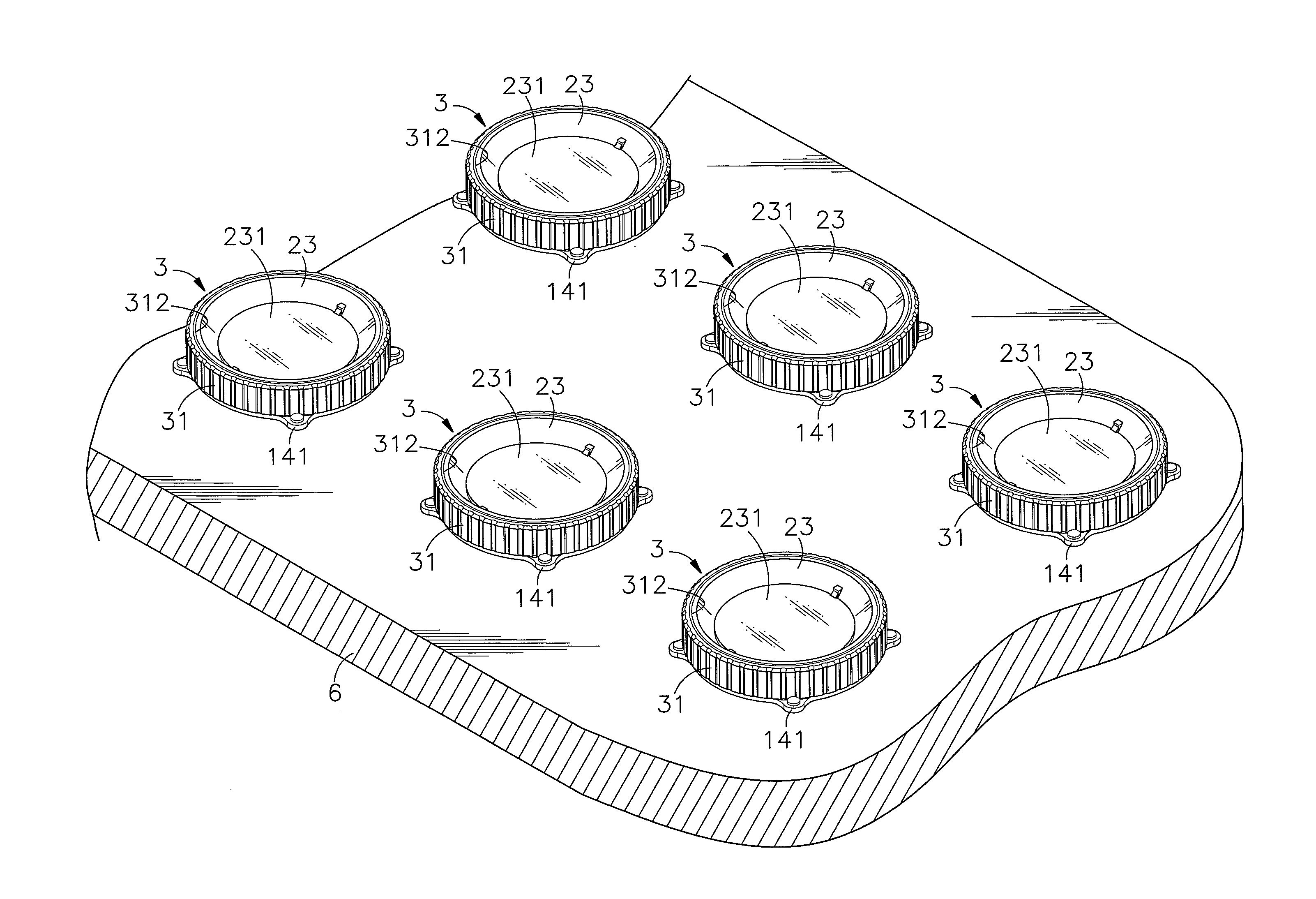
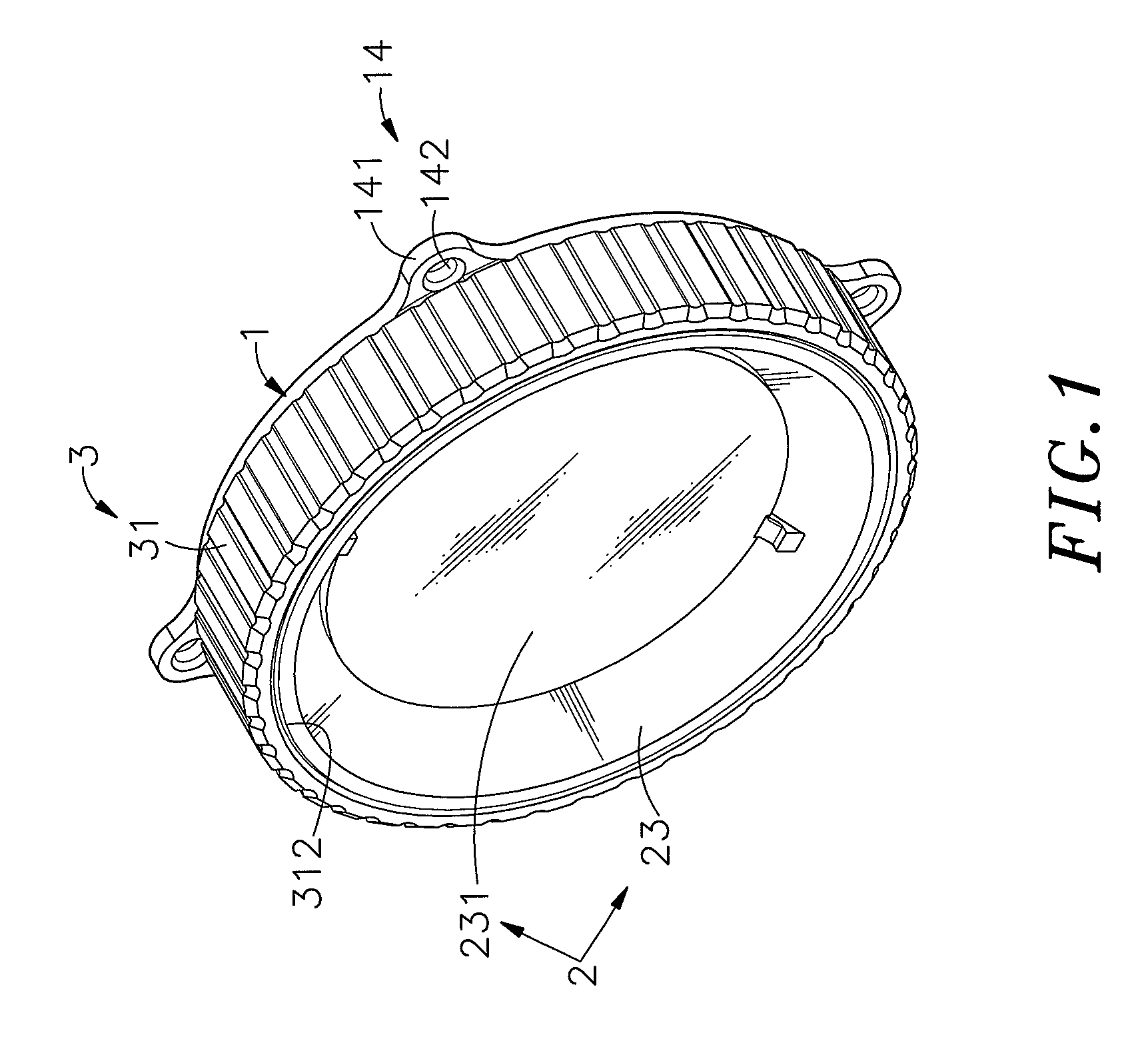
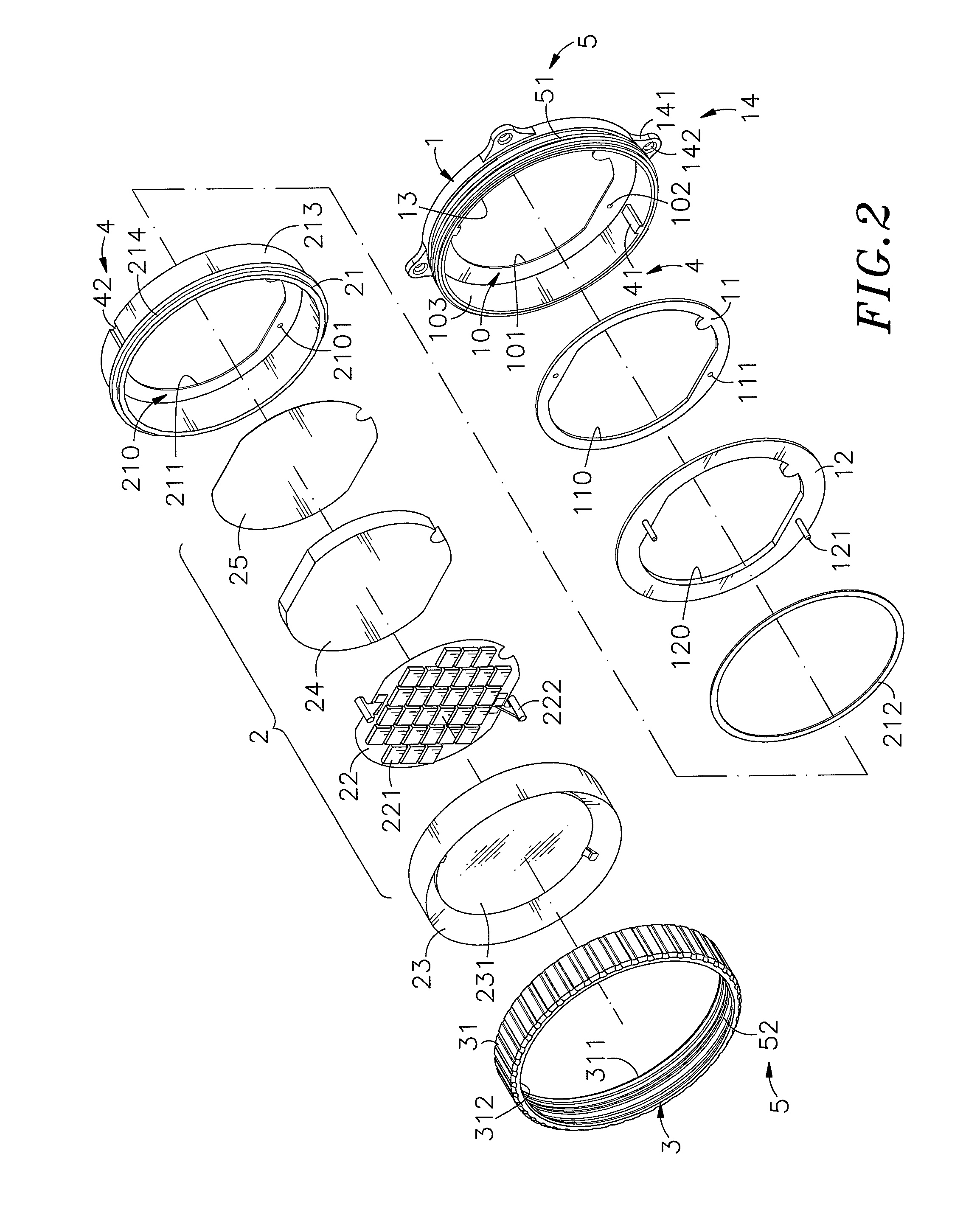
[0025]Referring to FIGS. 1˜5, a light-emitting unit adapter module in accordance with the present invention is shown comprising a mounting base 1, a light-emitting unit 2, a holding-down device 3, and a connection unit 5.

[0026]The mounting base 1 has an accommodation chamber 10 defined therein, a center opening 101 cut through the bottom wall of the accommodation chamber 10, a plurality of locating holes 102 located on the bottom wall of the accommodation chamber 10 and spaced around the center opening 101, a connection portion 13 extending around the periphery of the accommodation chamber 10 and a plurality of mounting portions 14, for example, mounting lugs 141 perpendicularly extended from and equiangularly spaced around the connection portion 13. Further, the mounting base 1 accommodates a spacer member 11 and a circuit board 12 in the accommodation chamber 10. The spacer member 11 is set between the bottom wall of the accommodation chamber 10 and one side of the circuit board 1...


PUM


Abstract

A light-emitting unit adapter module includes a mounting base for mounting, a circuit board accommodated in the mounting base and having electrode pins connectable to an external power source, a light-emitting unit mountable in the mounting base, and a holding-down device fastenable to the mounting base to hold down the light-emitting unit, keeping the tubular electrodes of the light-emitting unit in positive contact with the electrode pins of the circuit board for power input and the heat sink of the light-emitting unit suspending outside the mounting base for quick dissipation of waste heat during operation of the light-emitting devices of the light-emitting unit.

Description

[0001]This application claims the priority benefit of Taiwan patent application number 098120141, filed on Jun. 16, 2009.BACKGROUND OF THE INVENTION[0002]1. Field of the Invention[0003]The present invention relates to light-emitting device mounting technology and more particularly, to a light-emitting unit adapter module, which facilitates mounting and dismounting of the light-emitting unit, avoids heat accumulation and effectively seals off outside moisture.[0004]2. Description of the Related Art[0005]In order to slow down and eventually reverse global warming, many countries around the world are actively applying energy saving and carbon reduction action plains. These action plains may include planting trees and using power-saving electronic products. Nowadays, LED (light emitting diode) has been intensively used in lamp bulb, lamp tube, desk lamp, hand light, backlight, vehicle light and many other lighting fixtures and electronic products. However, only high-performance light-em...

Claims


Application Information

Patent Timeline
IPC IPC(8): F21S4/00
CPCF21K9/00F21S2/005F21V31/005F21V17/12F21V29/70F21V29/713F21Y2105/10F21Y2115/10
Inventor LIN, HSUAN-CHIHCHEN, HONG-LONG
Owner KWO GER METAL TECH
Why Eureka
Try Eureka