Cooling Structure For Gas Turbine Transition Duct

a transition duct and cooling structure technology, applied in the direction of machines/engines, liquid fuel engines, stators, etc., can solve the problems of temperature-limiting stress levels in the transition duct, premature stress and cracking along various turbomachinary components,

Inactive Publication Date: 2010-12-16
SIEMENS ENERGY INC
View PDF20 Cites 47 Cited by
  • Summary
  • Abstract
  • Description
  • Claims
  • Application Information

AI Technical Summary

Problems solved by technology

The hot working gas, however, may produce combustor section and turbine section component metal temperatures that exceed the maximum operating rating of the alloys from which the combustor section and turbine section are made and, in turn, may induce premature stress and cracking along various turbomachinary components.
In particular, the high firing temperatures generated in the combustion section, combined with the complex geometry of the transition duct, can lead to temperature-limiting levels of stress within the transition duct.

Method used


Image

  • Cooling Structure For Gas Turbine Transition Duct
  • Cooling Structure For Gas Turbine Transition Duct
  • Cooling Structure For Gas Turbine Transition Duct

Examples


Embodiment Construction

[0017]In the following detailed description of the preferred embodiment, reference is made to the accompanying drawings that form a part hereof, and in which is shown by way of illustration, and not by way of limitation, a specific preferred embodiment in which the invention may be practiced. It is to be understood that other embodiments may be utilized and that changes may be made without departing from the spirit and scope of the present invention.

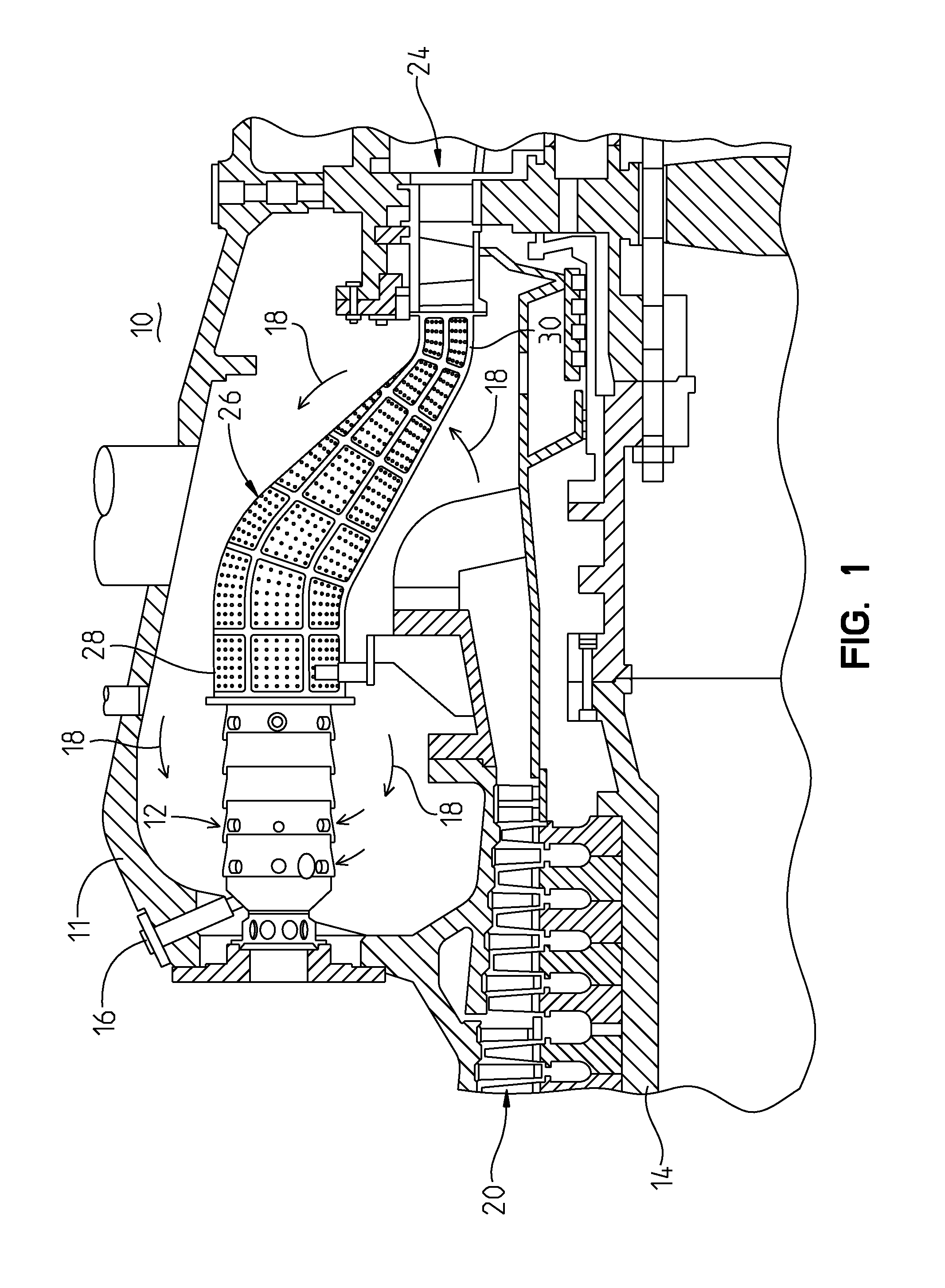
[0018]Referring to FIG. 1, an exemplary gas turbine engine 10 is illustrated for the purpose of illustrating the present invention. However, it should be understood that this invention may be applied to various turbine engine constructions and is not limited to the particular construction shown herein.

[0019]The engine 10 includes a casing 11 and a plurality of combustors 12 (only one illustrated) supported in the casing 11 and arranged in an annular array about a rotatable shaft 14. The combustors 12 receive a combustible fuel from a fue...


PUM


Abstract

A transition duct for conveying hot combustion gas from a combustor to a turbine in a gas turbine engine. The transition duct includes a panel including a middle subpanel, an inner subpanel spaced from an inner side of the middle subpanel to form an inner plenum, and an outer subpanel spaced from an outer side of the middle subpanel to form an outer plenum. The outer subpanel includes a plurality of outer diffusion holes to meter cooling air into the outer plenum. The middle subpanel includes a plurality of effusion holes to allow cooling air to flow from the outer plenum to the inner plenum. The inner subpanel includes a plurality of film holes for passing a flow of cooling air from the inner plenum through the film holes into an axial gas flow path adjacent to the inner side of the inner subpanel.

Description

FIELD OF THE INVENTION[0001]The present invention relates generally to gas turbine engines and, more particularly, to a transition duct for conveying hot combustion gas from a combustor to a turbine section of a gas turbine engine.BACKGROUND OF THE INVENTION[0002]Combustion turbines generally comprise a casing for housing a compressor section, a combustor section and a turbine section. Each one of these sections comprise an inlet end and an outlet end. A combustor transition duct is mechanically coupled between the combustor section outlet end and the turbine section inlet end to direct a working gas from the combustor section into the turbine section.[0003]The working gas is produced by combusting an air / fuel mixture. A supply of compressed air, originating from the compressor section, is mixed with a fuel supply to create a combustible air / fuel mixture. The air / fuel mixture is combusted in the combustor to produce a high temperature and high pressure working gas. The working gas i...

Claims


Application Information

Patent Timeline
Patent Type & Authority Applications(United States)
IPC IPC(8): F01D1/00
CPCF01D9/023F05D2260/201F05D2260/202F05D2260/203
Inventor CHARRON, RICHARDSNYDER, GARYLANDIS, KENNETH K.
Owner SIEMENS ENERGY INC
Why Eureka
Try Eureka