Eureka AIR delivers breakthrough ideas for toughest innovation challenges, trusted by R&D personnel around the world.

Ultrasound transducer with improved acoustic performance

a technology of ultrasound transducer and acoustic spectrum, which is applied in the field of ultrasound transducers, can solve the problems of reducing the image quality of medical diagnostic images, long ring-down and other acoustic artifacts, and achieve the effect of improving the acoustic performance of ultrasound transducers and reducing artifacts within the acoustic spectrum

Active Publication Date: 2010-12-16
GENERAL ELECTRIC CO
View PDF13 Cites 88 Cited by
  • Summary
  • Abstract
  • Description
  • Claims
  • Application Information

AI Technical Summary

Benefits of technology

"The invention is a method and apparatus for improving the acoustic performance of an ultrasound transducer by reducing artifacts within the acoustic spectrum. The apparatus includes an interposer layer for coupling an array of transducer elements to a beam forming electronics package. The interposer layer has a lower acoustic impedance than the dematching layer and the acoustic layer, which helps to reduce echoes and improve the quality of ultrasound images. The method includes steps of adding vias to the interposer layer and filling them with electrically conductive material to enhance the electrical connection between the transducer elements and the electronics package. The invention is particularly useful for invasive probes where the interposer layer helps to improve the acoustic performance of the transducer."

Problems solved by technology

Such applications are quite demanding, requiring very small transducer packages that can nevertheless collect large amounts of information.
With this method of connection, however, acoustic energy from the array propagates into the electronics, leading to artifacts within the acoustic spectrum ultimately reducing the image quality of a medical diagnostic image.
This acoustic energy will reverberate with minimal loss within the silicon substrate and can return to the acoustic array causing long ring-down and other acoustic artifacts.
These artifacts reduce the quality of the acoustic image such as those useful in medical diagnostic imaging.
However, the high impedance dematching layer itself does not reduce these artifacts sufficiently to provide the preferred image quality.

Method used


Image

  • Ultrasound transducer with improved acoustic performance
  • Ultrasound transducer with improved acoustic performance
  • Ultrasound transducer with improved acoustic performance

Examples


Embodiment Construction

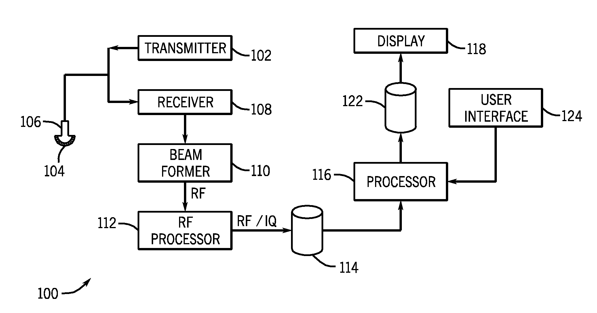
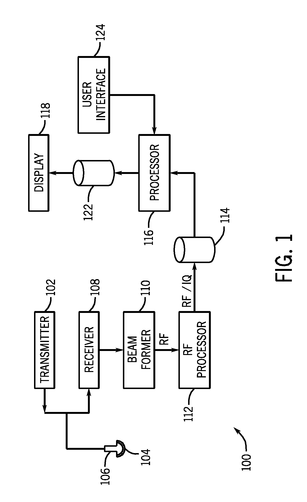
[0021]FIG. 1 illustrates an ultrasound system 100 including a transmitter 102 that drives an array of elements 104 (i.e., transducer elements) within an ultrasound transducer 106 to emit pulsed ultrasonic signals into a body. Each of the elements 104 corresponds to an acoustical stack (as shown in FIG. 3). The elements 104 may be arranged, for example, in one or two dimensions. A variety of geometries may be used. Each ultrasound transducer 106 has a defined center operating frequency and bandwidth. The ultrasonic signals are back-scattered from structures in the body, like fatty tissue or muscular tissue, to produce echoes that return to the elements 104. The echoes are received by a receiver 108. The received echoes are passed through beam-forming electronics 110, which performs beam-forming and outputs an RF signal. The RF signal then passes through an RF processor 112. Alternatively, the RF processor 112 may include a complex demodulator (not shown) that demodulates the RF signa...


PUM


Abstract

A system for improving the acoustic performance of an ultrasound transducer by reducing artifacts within the acoustic spectrum is disclosed. The system includes an acoustic layer having an array of acoustic elements, a dematching layer coupled to the acoustic layer and having an acoustic impedance greater than an acoustic impedance of the acoustic layer, and an interposer layer coupled to the dematching layer and comprising a substrate and a plurality of conductive element. The interposer layer is formed to have an acoustic impedance lower than the acoustic impedance of the dematching layer. The ultrasound transducer also includes an integrated circuit coupled to the interposer layer and electrically connected to the array of acoustic elements through the dematching layer and the interposer layer.

Description

BACKGROUND OF THE INVENTION[0001]The invention relates generally to ultrasound transducers and, more particularly, to a method and apparatus for improving the acoustic performance of an ultrasound transducer by reducing artifacts within the acoustic spectrum.[0002]Ultrasound transducers (i.e., ultrasound probes) have found application in medical imaging where an acoustic probe is held against a patient and the probe transmits and receives ultrasound waves. The received energy may, in turn, facilitate the imaging of the internal tissues of the patient. For example, transducers may be employed to image the heart of the patient. Increasingly, it has been desirable to minimize the size of ultrasound transducers to enable their use in intra-corporeal devices, such as trans-esophageal examination devices, laparoscopic examination devices, intra-cardiac examination devices, and the like. Such applications are quite demanding, requiring very small transducer packages that can nevertheless c...

Claims


Application Information

Patent Timeline
Patent Type & Authority Applications(United States)
IPC IPC(8): A61B8/14H10N30/00
CPCA61B8/483G10K11/002A61B8/4483
Inventor BAUMGARTNER, CHARLES EDWARDGELLY, JEAN-FRANCOISSMITH, LOWELLWOYCHIK, CHARLES G.LANTERI, FREDERICEDWARDSEN, STEPHENLEWANDOWSKI, ROBERT S.
Owner GENERAL ELECTRIC CO
Why Eureka
Eureka Blog
Learn More