Control device for internal combustion engine

a control device and internal combustion engine technology, applied in the field of internal combustion engine control apparatus, can solve the problems of inability to detect the failure of the intake-valve control apparatus correctly, the failure of the intake-valve control apparatus in operation, and the difference produced in cylinder pressure, so as to accurately detect the failure of the intake-valve control apparatus

Inactive Publication Date: 2010-12-16
TOYOTA JIDOSHA KK
View PDF8 Cites 8 Cited by
  • Summary
  • Abstract
  • Description
  • Claims
  • Application Information

AI Technical Summary

Benefits of technology

[0006]Accordingly, an object of the present invention is to provide a control apparatus for an internal combustion engine which includes an intake-valve control apparatus for controlling at least open timing of intake valves and which can accurately detect a failure of the intake-valve control apparatus.

Problems solved by technology

However, as described above, only when the engine is operated at high speed and / or under heavy load, a clear difference is produced in cylinder pressure during the expansion stroke between the case where the open and close timings of the intake valves are advanced and the case where the open and close timings of the intake valves are not advanced.
Accordingly, the apparatus described in the above-mentioned document has a problem in that a failure of the intake-valve control apparatus cannot be detected correctly in operation states other than the state where the engine is operated at high speed and / or under heavy load.
Therefore, the apparatus described in the above-mentioned document may fail to detect a failure of the intake-valve control apparatus correctly even when the engine is operated at high speed and / or under heavy load.

Method used


Image

  • Control device for internal combustion engine
  • Control device for internal combustion engine
  • Control device for internal combustion engine

Examples


Embodiment Construction

[0051]An embodiment of a control apparatus for an internal combustion engine according to the present invention will be described with reference to the drawings.

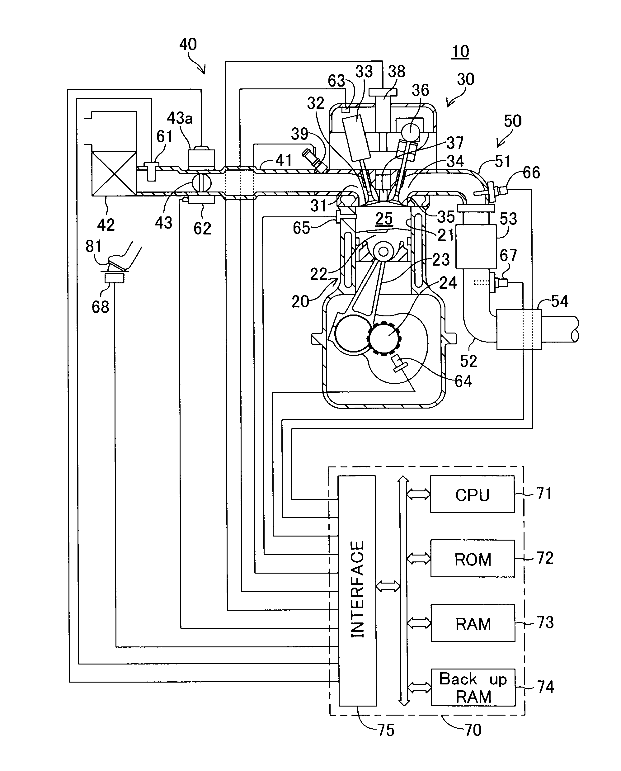
[0052]FIG. 1 schematically shows the configuration of a system configured such that a control apparatus according to an embodiment of the present invention is applied to a spark-ignition multi-cylinder (4-cylinder) four-cycle internal combustion engine 10. This internal combustion engine 10 includes a cylinder block section 20 including a cylinder block, a cylinder block lower-case, an oil pan, etc.; a cylinder head section 30 fixed on the cylinder block section 20; an intake system 40 for supplying gasoline gas mixture to the cylinder block section 20; and an exhaust system 50 for discharging exhaust gas from the cylinder block section 20 to the exterior of the engine.

[0053]The cylinder block section 20 includes cylinders 21, pistons 22, connecting rods 23, and a crankshaft 24. Each of the pistons 22 reciprocates within the...


PUM


Abstract

In this apparatus, maintaining control (time t1 to t2) which instructs fixing of the open timing VVT of an intake valve is executed in a predetermined low load state. Subsequently, there are executed changing control which instructs changing of the open timing VVT by a predetermined amount (time t2), and maintaining control which again instructs fixing of the open timing VVT of the intake valve (time t2 to t3). An intake-valve control apparatus is determined to be “anomalous” when an change amount Δave (=ave2−ave1) between the average ave1 of a large number of sample values of ΔMFBβ (combustion percentage increase amount within a predetermined crank angle range in an expansion stroke) during the maintaining control before execution of the changing control and the average ave2 of a large number of sample values of ΔMFBβ during the maintaining control after execution of the changing control is less than a predetermined value C.

Description

TECHNICAL FIELD[0001]The present invention relates to a control apparatus for an internal combustion engine including an intake-valve control apparatus for controlling at least open timing of intake valves and, more particularly, to detection of a failure of the control apparatus for an internal combustion engine (the intake-valve control apparatus).BACKGROUND ART[0002]Conventionally, there has been widely known an internal combustion engine equipped with an intake-valve control apparatus capable of controlling open and close timings (and the maximum lift amount) of the intake valves (see, for example, Japanese Patent Application Laid-Open (kokai) No. H6-317116). As is known, when the open and close timings of the intake valves are advanced, a period during which both the intake valves and the exhaust valves are maintained in an opened state (hereinafter referred to as an “overlap period”) is prolonged, whereby the efficiency of charging air into each combustion chamber can be incre...

Claims


Application Information

Patent Timeline
Patent Type & Authority Applications(United States)
IPC IPC(8): F02D41/00F01L1/34
CPCF02D13/0234F02D35/02F02D35/023F02D41/221F02D2250/14F02P5/153F02D13/0215F02D2041/001Y02T10/12Y02T10/40
Inventor MORIYA, HIDENORITADOKORO, RYO
Owner TOYOTA JIDOSHA KK
Why Eureka
Try Eureka