Testing Method Detecting Incorrectly Connected Antenna Contacts

a technology of incorrect connection and test method, applied in the direction of electrical connection testing, transmission, instruments, etc., can solve problems such as the inability to detect the perfect connection

Inactive Publication Date: 2013-09-19
ST ERICSSON SA
View PDF1 Cites 8 Cited by
  • Summary
  • Abstract
  • Description
  • Claims
  • Application Information

AI Technical Summary

Benefits of technology

[0010]The object of the present invention is to alleviate at least partly the above mentioned drawbacks.

Problems solved by technology

This imperfect connection may work in certain use conditions and may not work in other use conditions.

Method used


Image

  • Testing Method Detecting Incorrectly Connected Antenna Contacts
  • Testing Method Detecting Incorrectly Connected Antenna Contacts
  • Testing Method Detecting Incorrectly Connected Antenna Contacts

Examples


Embodiment Construction

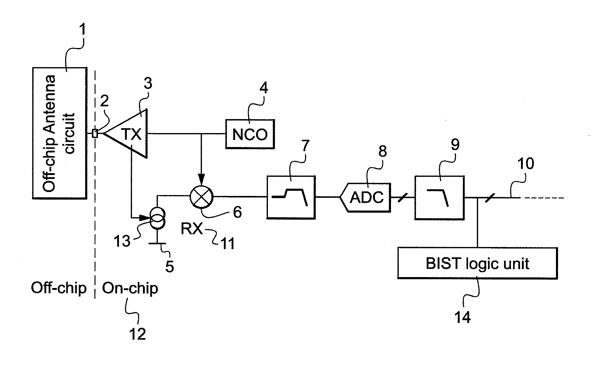
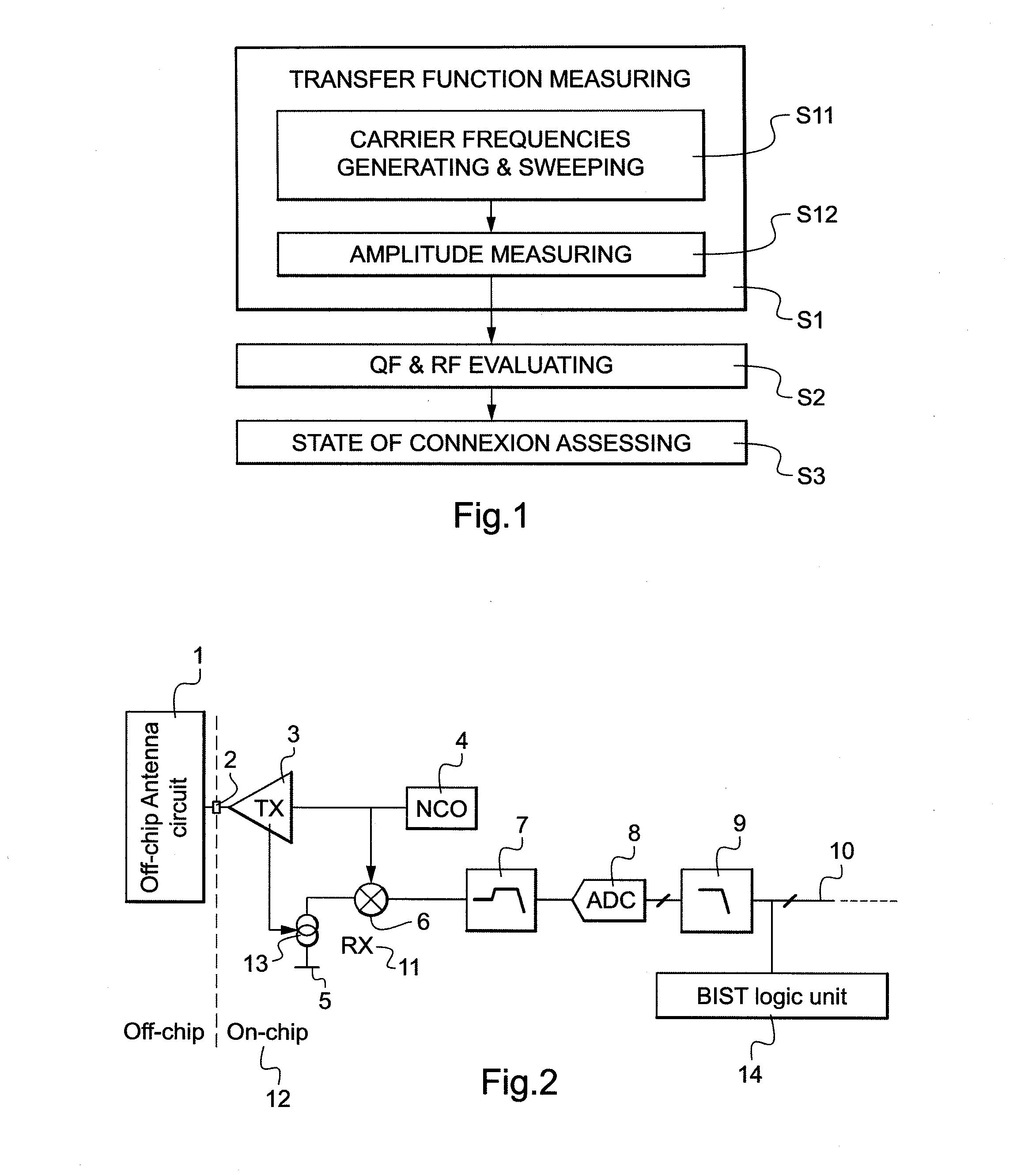
[0057]FIG. 1 shows an example of a testing method according to an embodiment of the invention. BIST method comprises several successive steps. First a transfer function measuring step S1, then a QF (quality factor) and RF (resonance frequency) evaluating step S2, and afterwards a state of connection assessing step S3. Transfer function measuring step S1 is subdivided in two substeps S11 and S12.

[0058]In substep S11, there are generated carrier frequencies, with a sweeping of those carrier frequencies over a predetermined frequency range. This predetermined frequency range is chosen broad enough to cover a sufficient portion of the transfer function including the effective resonance frequency that can be shifted relatively to the theoretical resonance frequency which corresponds to ideal connection between ideal circuit and ideal antenna. In substep S11, generating and sweeping carrier frequencies over a predetermined frequency range takes place at the input of a transmitter of on-ch...


PUM


Abstract

The invention concerns a testing method detecting misconnected mechanical contacts between off-chip antenna and on-chip antenna circuit, wherein the testing method is a Built-In Self-Test method including a step of measuring at least one electrical parameter of on-chip antenna circuit connected to off-chip antenna which is representative of state of connection of said mechanical contacts.

Description

FIELD OF THE INVENTION[0001]The invention relates to testing methods detecting incorrectly connected contacts between off-chip antenna and on-chip antenna circuit.BACKGROUND OF THE INVENTION[0002]There exist several concepts of testing methods detecting incorrectly connected contacts between off-chip antenna and on-chip antenna circuit. All these existing techniques have been developed for testing state of connection of electrical contacts. Electrical contacts are for example soldered contacts between off-chip antenna and on-chip antenna circuit. All these existing testing concepts present weaknesses.[0003]According to one of these testing concepts, antenna circuit impedance is measured. A peak detector is used that is integrated in the power amplifier block of the transmitter. The peak voltage of the transmitted signal is measured on-chip. By measuring the peak voltage, the load impedance at the antenna circuit connection pads is calculated and verified against the specified range ...

Claims


Application Information

Patent Timeline
Patent Type & Authority Applications(United States)
IPC IPC(8): H04B17/00
CPCH04B17/00G01R29/10H04B17/14H04B17/102G01R31/041G01R31/67
Inventor DHAYNI, ACHRAF
Owner ST ERICSSON SA
Why Eureka
Try Eureka