

Optical network fault detection device based on noise signals and detection method thereof
A technology for noise signal and fault detection, applied in optical network fault detection device and its detection field, can solve problems such as low resolution and complex structure, and achieve the effects of high spatial resolution, simplified device and convenient operation
- Summary
- Abstract
- Description
- Claims
- Application Information
AI Technical Summary
Problems solved by technology
Method used
Image


Examples
no. 1 example
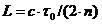
[0032] An optical network fault detection device based on a noise signal is implemented in the present invention, and the device is suitable for a wavelength division multiplexed passive optical network.
[0033] Such as figure 1 As mentioned above, a schematic diagram of the structure of the passive optical network is given, wherein the optical line terminal OLT emits communication signals, and the signals are distributed through the communication wavelength division multiplexer in the optical distribution network unit ODN, and the distributed signals pass through the network The target path enters the optical network subscriber unit ONU.
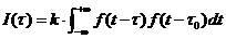
[0034] Such as figure 2 As mentioned above, a passive optical network detection device of the present invention is located at the OLT side and includes a noise source and a signal processing unit.
[0035] Such as image 3 Said, the noise source 1 of the present invention comes from the amplified spontaneous emission (ASE) noise o...
no. 2 example
[0039] On the basis of the first embodiment, the second embodiment such as Figure 4 As mentioned above, the signal processing unit is composed of a coupler I2, a reflective tunable filter 9, a photodetector I4, an A / D converter I6 and a signal processing device 8. Among them, one reference signal is filtered by the reflective adjustable filter 9 and then enters the photodetector I4 through the coupler I2, and the positioning is realized by performing an autocorrelation operation on the collected signal, and the other is the same as the first embodiment. In this embodiment, the transmissive tunable filter 3 is replaced by a reflective tunable filter 9, which can make the structure of the signal processing unit simpler than that of the first embodiment.
no. 3 example
[0041] On the basis of the first embodiment, the third embodiment such as Figure 5 As mentioned above, the signal processing unit is composed of coupler I2, coupler II10, transmission tunable filter 3, photodetector II5, A / D converter II7 and signal processing device 8. The reference signal and the returned detection signal are coupled into one signal through the coupler I2 and the coupler II10, and the collected signal is subjected to an autocorrelation operation, and the others are the same as the first embodiment. In this embodiment, the structure is simplified by coupling optical paths without replacing the transmissive tunable filter 3 .
PUM
 Abstract
Description
Claims
Application Information