Device and method for mounting vehicle instrument panel

a vehicle instrument and mounting device technology, applied in the direction of programmed manipulators, manufacturing tools, transportation and packaging, etc., can solve the problems of difficult positioning of the heavy instrument panel assembly, the difficulty of controlling the operation of the gantry robot, and the effect of reducing the load imposed on the second working mechanism by the instrument panel

Inactive Publication Date: 2010-12-23
HONDA MOTOR CO LTD
View PDF0 Cites 22 Cited by
  • Summary
  • Abstract
  • Description
  • Claims
  • Application Information

AI Technical Summary

Benefits of technology

[0008]The present invention has been made to solve the above problems. It is an object of the present invention to provide an apparatus for and a method of installing a vehicle instrument panel quickly and efficiently in the passenger compartment of a motor vehicle.
[0015]According to the present invention, the first working mechanism has an assistive function to bear the weight of the instrument panel. Accordingly, when the second working mechanism works on the instrument panel, the load imposed on the second working mechanism by the instrument panel is effectively reduced. The second working mechanism can thus be reduced in size, so that the installing apparatus can easily be reduced in size and simplified as a whole, and the process of installing the instrument panel can be performed quickly and efficiently as the effect of inertia is reduced.
[0016]When the second working mechanism is to be shut down for maintenance, etc., the second working mechanism is separated from the first working mechanism and placed in a retracted position. Then, the worker can easily install the instrument panel under the assistive action of the first working mechanism.
[0017]Furthermore, the second working mechanism has the bolt tightening means for fastening with bolts the instrument panel at the instrument panel installing position in the vehicle. Therefore, the floor space occupied by the entire equipment can be reduced, resulting in an increased space efficiency.

Problems solved by technology

It is considerably complex to control the operation of the gantry robot 6, and it is difficult to position the heavy instrument panel assembly 3 at the given installing position.

Method used


Image

  • Device and method for mounting vehicle instrument panel
  • Device and method for mounting vehicle instrument panel
  • Device and method for mounting vehicle instrument panel

Examples


first embodiment

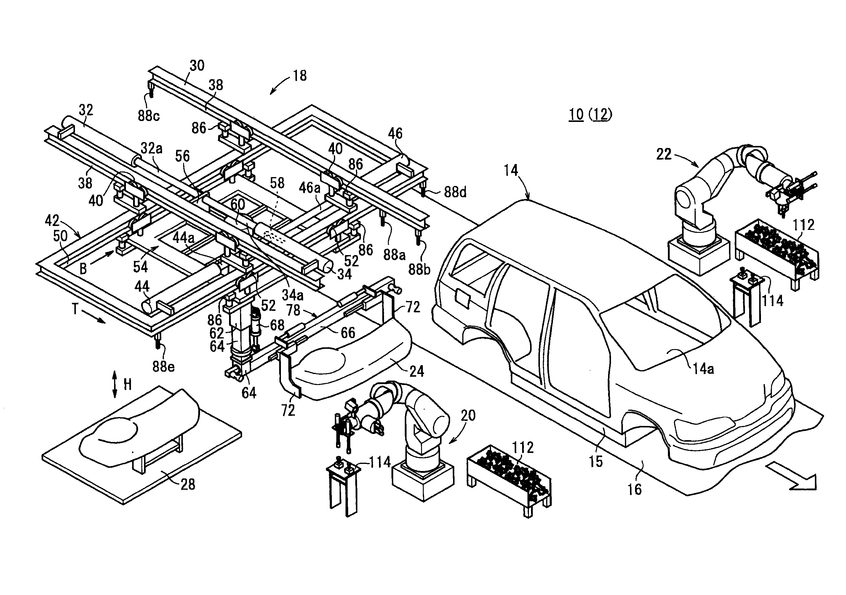
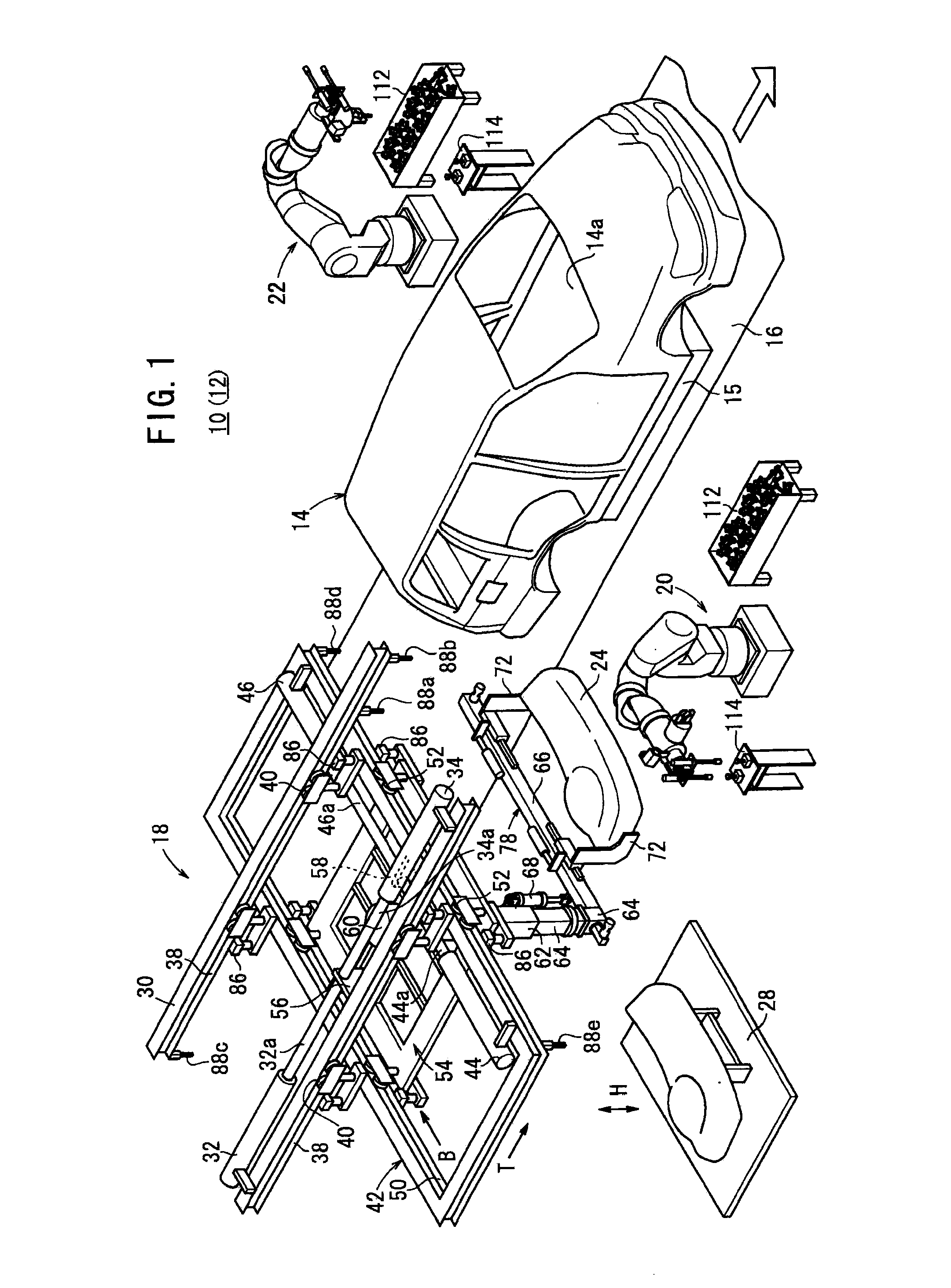
[0032]FIG. 1 is a perspective view of an assembling line 12 where an apparatus 10 for installing a vehicle instrument panel according to the present invention is disposed.

[0033]The assembling line 12 includes a feed path 16 for pitch-feeding an automobile body (motor vehicle) 14 placed on a carriage 15 to an instrument panel installing station. The installing apparatus 10 comprises an assistive machine (first working mechanism) 18, a right working robot (second working mechanism) 20 and a left working robot (second working mechanism) 22 which are disposed one on each side of the automobile body 14. The installing apparatus 10 automatically installs an instrument panel 24 in a passenger compartment 14a of the automobile body 14.

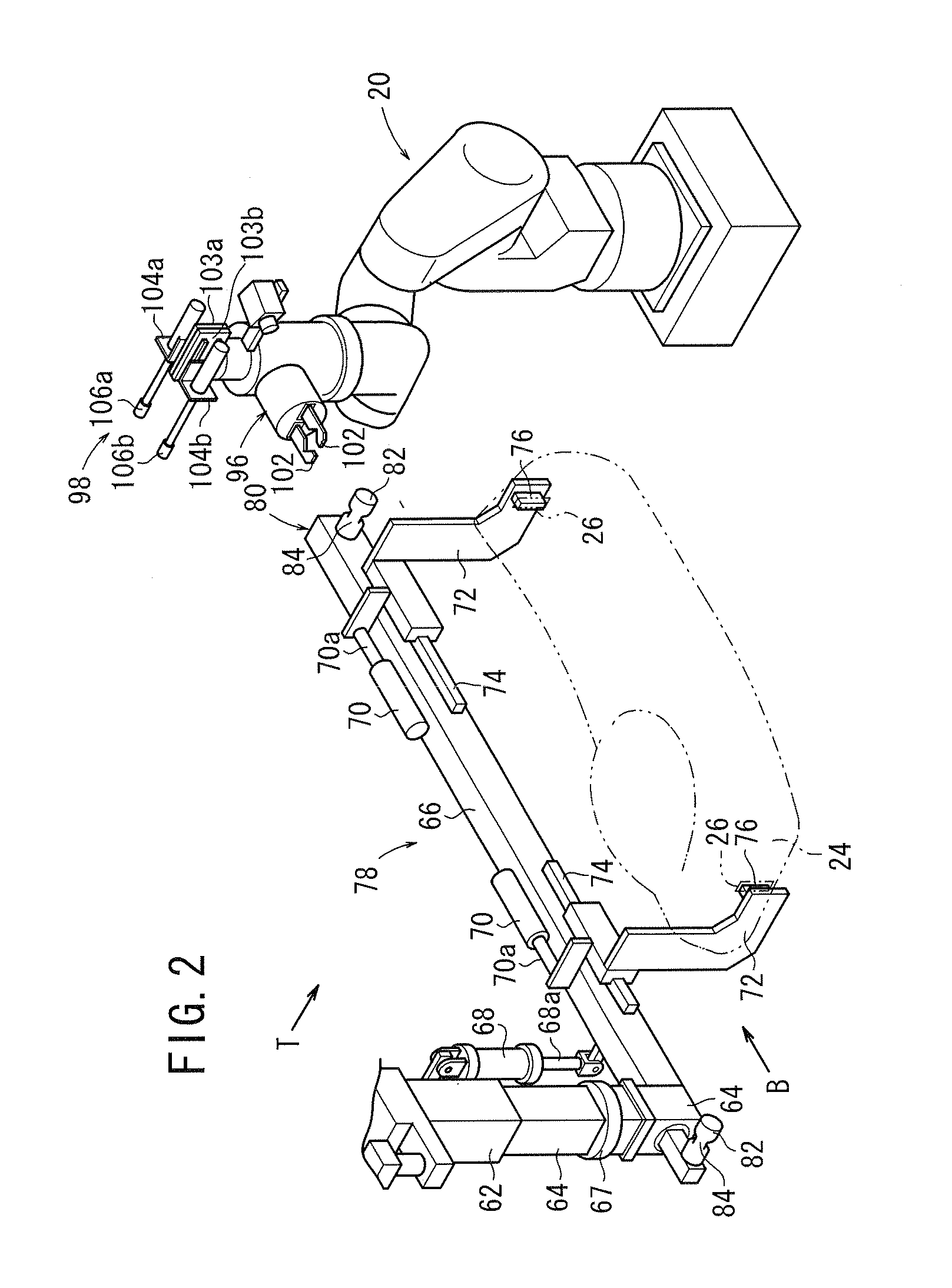
[0034]The instrument panel 24 has two reference holes (not shown) defined in each of its opposite ends in the longitudinal directions thereof (in the transverse directions of the automobile body), and also has a grip hole 26 (see FIG. 2) defined in each of its...

second embodiment

[0089]The hands 96 of the working robots 20, 22 grip the movable joint members 128. The movable joint members 128 can switch to either one of the two angular positions depending on the configuration, etc. of the instrument panel 24. the installing apparatus can easily cope with instrument panels 24 of different types.

[0090]FIG. 13 is a perspective view of an assistive machine 130 of an apparatus for installing a vehicle instrument panel according to a third embodiment of the present invention. Those components of the assistive machine 130 which are identical to those of the assistive machine 18 of the installing apparatus 10 according to the first embodiment are denoted by identical reference characters, and will not be described in detail below.

[0091]The assistive machine 130 includes a propulsive motor 134 that is movable back and forth along a lower portion of the first frame 30 by a rack and pinion means 132. The propulsive motor 134 is fixed to the second frame 42. The second ...

third embodiment

[0092] the instrument panel gripping means 78 for gripping the instrument panel 24 is assistively actuated in the direction indicated by the arrow T and the direction indicated by the arrow B when the propulsive motors 134, 138 are energized. Based on ON / OFF signals from the first through fifth limit switches 88a through 88e, the instrument panel gripping means 78 can be positioned accurately and reliably at a desired position.

[0093]Specifically, the instrument panel 24 is gripped by the instrument panel gripping means 78. After the instrument panel gripping means 78 has reached an upper end position, the propulsive motor 134 is energized to cause the second frame 42 and the third frame 54 to move the instrument panel gripping means 78 in the direction indicated by the arrow T.

[0094]When the first limit switch 88a is turned on, the propulsive motor 134 is de-energized, thereby placing the instrument panel 24 in a panel putting position. For returning the instrument panel gripping me...


PUM

PropertyMeasurementUnit
weightaaaaaaaaaa
sizeaaaaaaaaaa
movementaaaaaaaaaa

Abstract

A device for mounting a vehicle instrumental panel has an assist machine and work robots. The assist machine has instrument panel holding means for holding an instrument panel, conveys the instrument panel, and has an assist function for holding the weight of the instrument panel. The work robots have connection means removably connected to the instrument panel holding means and operate the instrument panel holding means to place the instrument panel in a vehicle interior.

Description

TECHNICAL FIELD[0001]The present invention relates to an apparatus (device) for and a method of installing (mounting) a vehicle instrument panel in the passenger compartment of a motor vehicle.BACKGROUND ART[0002]Automobile assembling lines, for example, carry out a process of automatically installing an instrument panel, which is one of heavy components, into the passenger compartment of an automobile body using a robot.[0003]An apparatus for installing an instrument panel assembly disclosed in Japanese Laid-Open Patent Publication No. 05-139350, for example, is known for use in such a process. As shown in FIG. 14, in the installing apparatus, a line 4 for supplying instrument panel assemblies 3 is provided in parallel to an assembling line 2 which feeds automobile bodies 1.[0004]The supplying line 4 includes three types of assembling tools 5a, 5b, 5c disposed at the terminal end thereof. Appropriate instrument panel assemblies 3 are fed respectively to the assembling tools 5a, 5b,...

Claims


Application Information

Patent Timeline
Patent Type & Authority Applications(United States)
IPC IPC(8): B23P19/04B23P17/00B23P11/00
CPCB25J5/04B25J9/0084B25J9/0093B25J13/085B25J19/023Y10T29/53061Y10T29/49947Y10T29/53539Y10T29/49826Y10T29/49998Y10T29/53974B62D65/14
Inventor SUGIMOTO, TOMOHIROTAKAHASHI, MITSUGUMARUO, MASARU
Owner HONDA MOTOR CO LTD
Why Eureka
Try Eureka