Two stage vibration isolator

a technology of vibration isolation and isolator, which is applied in the field of vibration isolation systems, can solve the problems of satellite payloads that are sensitive to vibrations, difficult for a single passive isolation system to isolate both types of vibration, and often experience unmitigated large-amplitude vibrations

Active Publication Date: 2010-12-23
HONEYWELL INT INC
View PDF42 Cites 34 Cited by
  • Summary
  • Abstract
  • Description
  • Claims
  • Application Information

AI Technical Summary

Problems solved by technology

Such payloads can be sensitive to vibrations.
It can be difficult for a single passive isolation system to isolate both types of vibration.
Consequently, a satellite payload will frequently experience unmitigated large-amplitude vibrations during launch to orbit.
The reinforcing features require additional volume in the payload area and impose additional energy costs during launch.
Additionally, while useful during launch, once in orbit the reinforcing features or structures typically have no utility.

Method used


Image

  • Two stage vibration isolator
  • Two stage vibration isolator
  • Two stage vibration isolator

Examples


Embodiment Construction

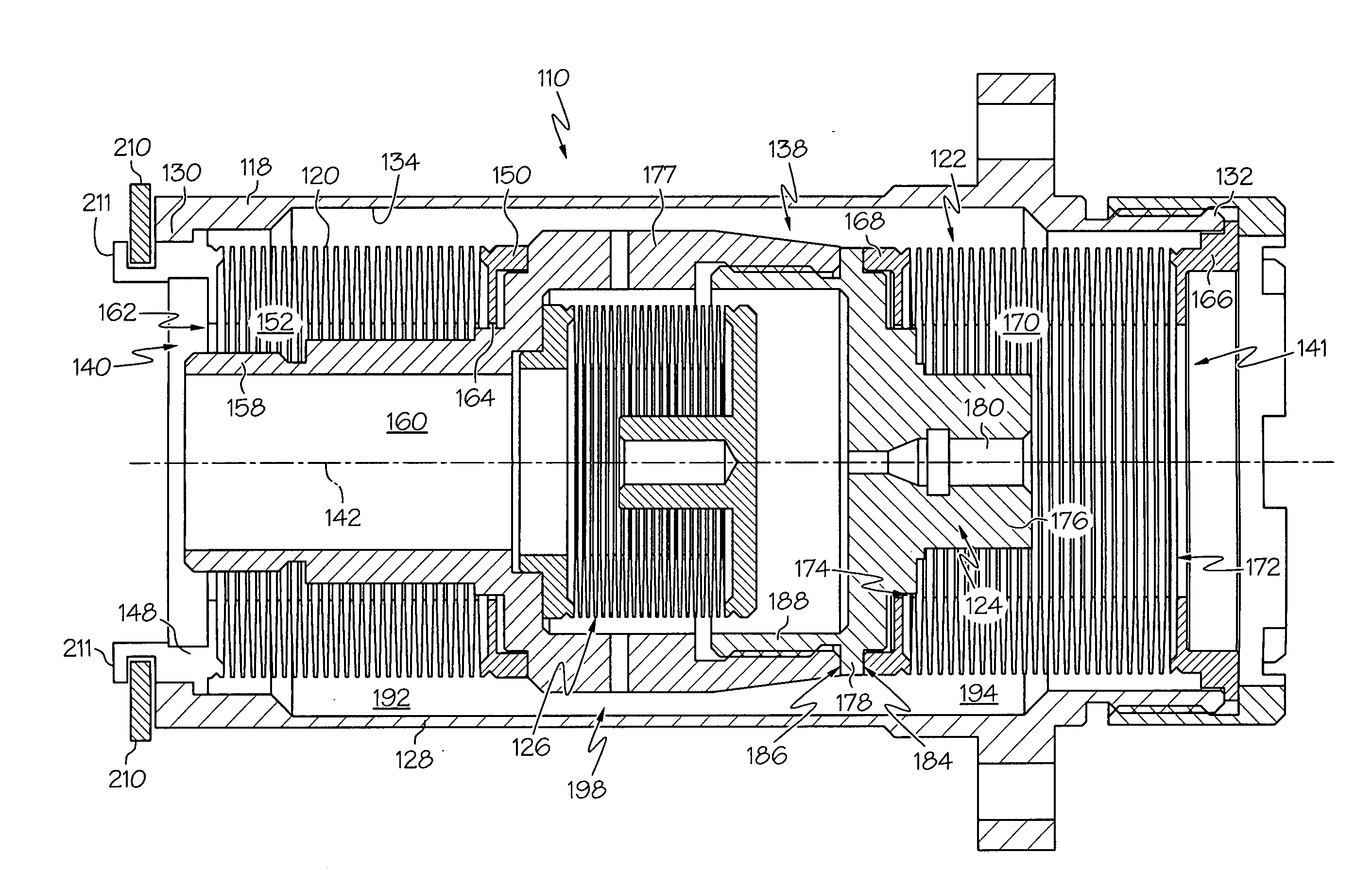
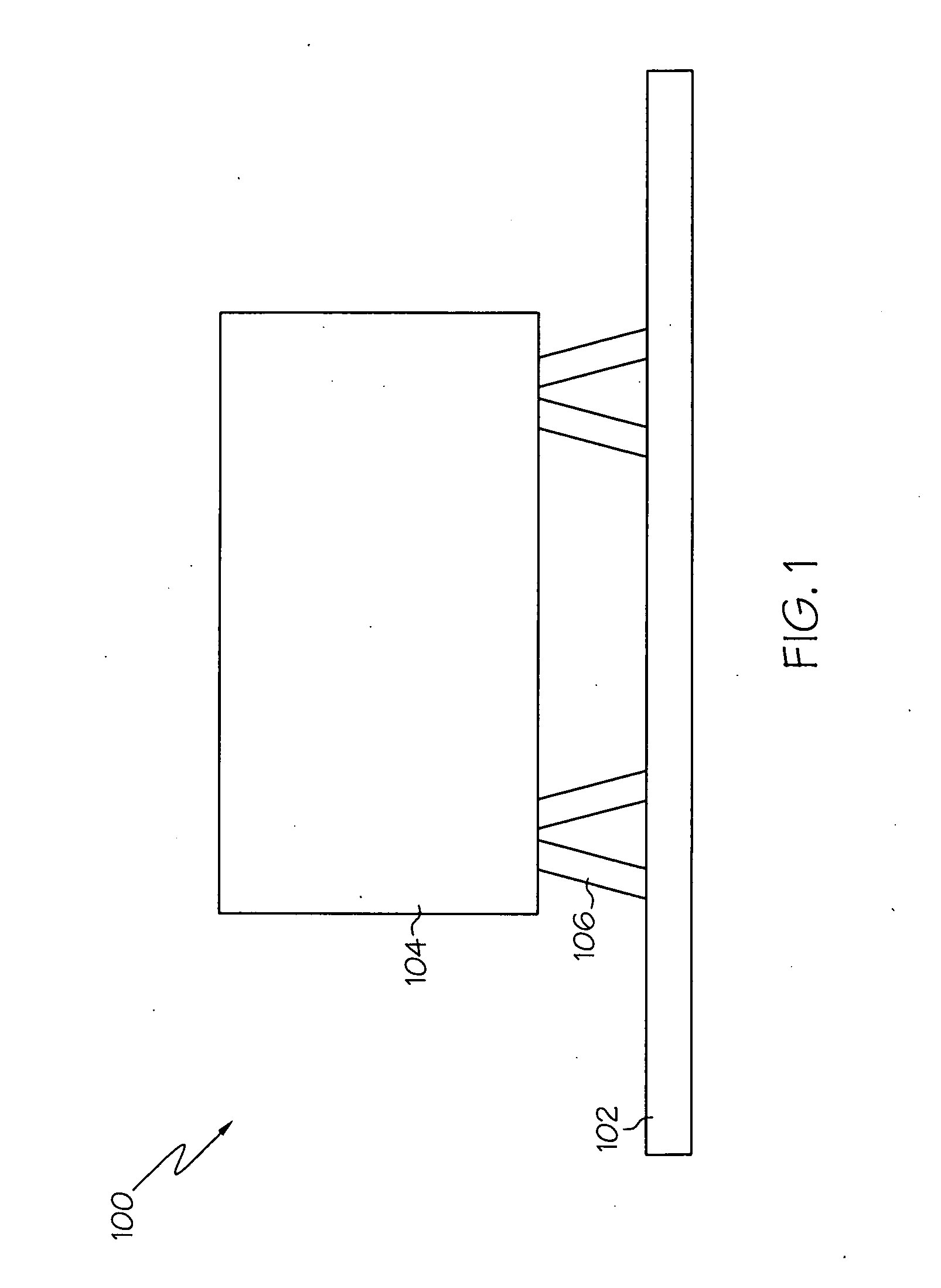
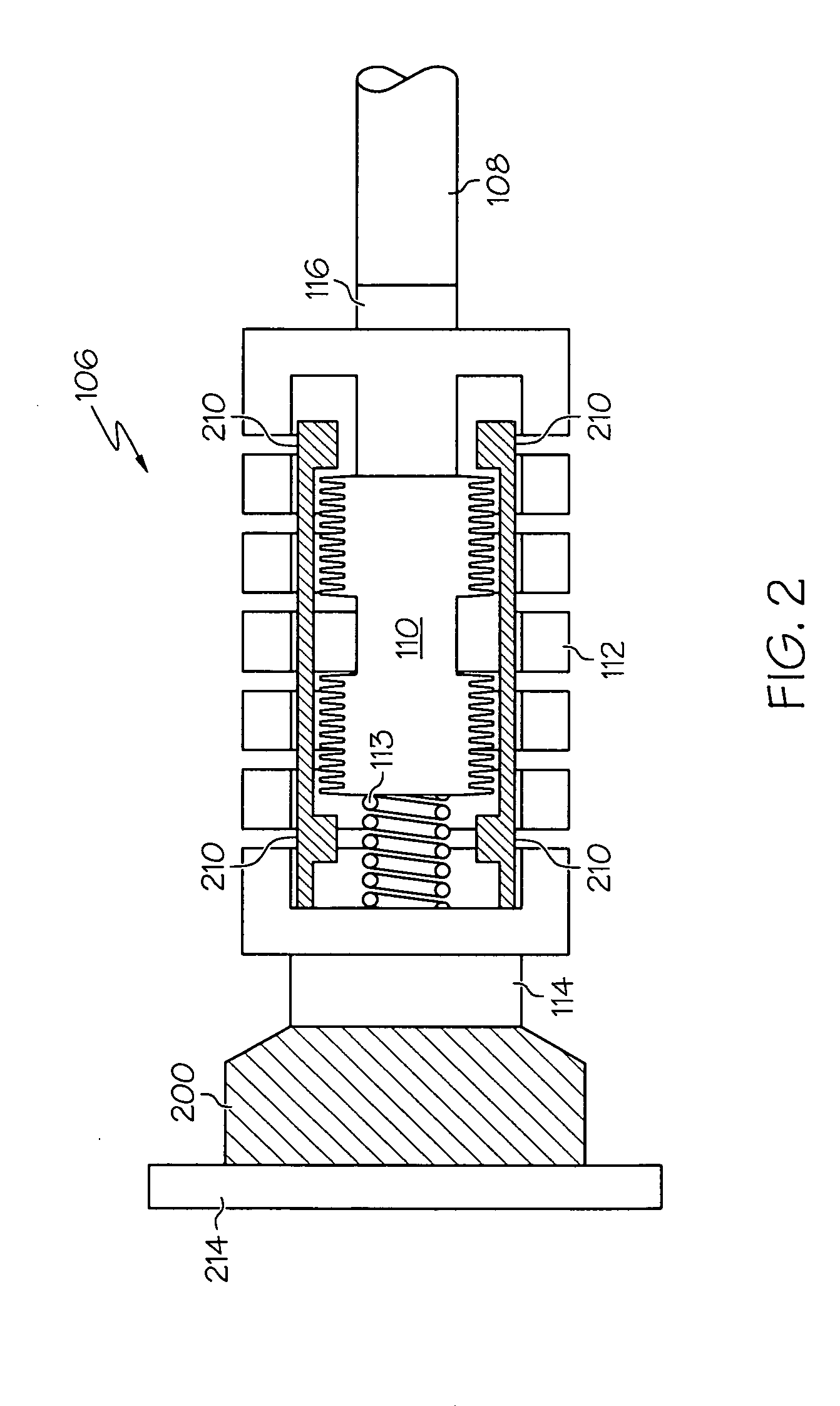
[0015]The following detailed description is merely illustrative in nature and is not intended to limit the embodiments of the subject matter or the application and uses of such embodiments. As used herein, the word “exemplary” means “serving as an example, instance, or illustration.” Any implementation described herein as exemplary is not necessarily to be construed as preferred or advantageous over other implementations. Furthermore, there is no intention to be bound by any expressed or implied theory presented in the preceding technical field, background, brief summary or the following detailed description.

[0016]“Coupled”—The following description refers to elements or nodes or features being “coupled” together. As used herein, unless expressly stated otherwise, “coupled” means that one element / node / feature is directly or indirectly joined to (or directly or indirectly communicates with) another element / node / feature, and not necessarily mechanically. Thus, although the schematic s...


PUM


Abstract

A vibration isolating system is disclosed. The vibration isolating system comprises a passive mechanical system comprising a damping assembly, a first resilient member coupled in series with the damping assembly, and a second resilient member coupled in parallel with the series combination of the damping assembly and the first resilient member. The vibration isolating system further comprises a support member coupled in series with the passive mechanical system, a viscoelastic mount coupled to the support member, and a motion limiter coupled to the support member such that the passive mechanical system transmits a force to the support member when the passive mechanical undergoes longitudinal displacement greater than a predetermined displacement.

Description

TECHNICAL FIELD[0001]Embodiments of the subject matter described herein relate generally to vibration isolators. More particularly, embodiments of the subject matter relate to two-stage, passive vibration isolators.BACKGROUND[0002]Various systems and components operate in an environment where they are subject to vibrations from surrounding objects. Such systems and components typically exhibit improved performance and / or accuracy when the vibrations are reduced or removed. Some exemplary systems include satellite payloads, which can be subjected to both large-amplitude vibrations during the launch to orbit around the Earth, as well as small-amplitude vibrations at a different frequencies than the large amplitude vibration while operating in orbit. Such payloads can be sensitive to vibrations. They can therefore benefit from appropriate vibration isolation. Particularly, damping elements are included in the vibration isolation. One example of a passive damping and isolation system is...

Claims


Application Information

Patent Timeline
Patent Type & Authority Applications(United States)
IPC IPC(8): F16F11/00
CPCF16F9/16F16F9/22F16F2230/105F16F15/022F16F15/023F16F13/005
Inventor BOYD, JAMESHINDLE, TIMOTHYRUEBSAMEN, DALE THOMAS
Owner HONEYWELL INT INC
Why Eureka
Try Eureka