Reticle pod with isolation system

a technology of reticle and isolation system, which is applied in the direction of packaging goods, instruments, printing, etc., can solve the problems of unsatisfactory final products, euv photolithography reflective photomasks are susceptible to contamination and damage to a far greater degree than reticles used, and achieve enhanced shock and vibration isolation, enhanced shock and vibration absorption

Active Publication Date: 2009-10-27
ENTEGRIS INC
View PDF42 Cites 46 Cited by
  • Summary
  • Abstract
  • Description
  • Claims
  • Application Information

AI Technical Summary

Benefits of technology

[0018]It is a feature and advantage of preferred embodiments of the invention to provide enhanced shock and vibration isolation to the reticle.
[0019]It is a feature and advantage of preferred embodiments of the invention to provide enhanced shock and vibration absorption before such shock and vibration reaches the reticle contained therein.
[0020]It is a feature and advantage of preferred embodiments of the invention to provide a dual containment to the reticle with is particularly advantageous for utilizing the pod as both a shipping device and a device for storing the reticle within the fabrication facility particularly intermediate processing steps.

Problems solved by technology

Because of the tiny size of the critical elements of modern integrated circuits, it is essential that the operative surface of the reticle (i.e. the patterned surface) be kept free of contaminants that could either damage the surface or distort the image projected onto the photoresist layer during processing thereby leading to a final product of unacceptable quality.
Currently, the art does not provide pellicle materials that are transparent to EUV.
Consequently, the reflective photomask (reticle) employed in EUV photolithography is susceptible to contamination and damage to a far greater degree than reticles used in conventional photolithography.
Clearly, unnecessary and unintended contact with other surfaces during manufacturing, processing, shipping, handling, transport or storage is highly undesirable in view of the susceptibility of the delicate features on the patterned surface of the reticle to damage due to sliding friction and abrasion.
Secondly, any particulate contamination of the surface of the reticle will likely compromise the reticle to a degree sufficient to seriously affect any end product obtained from the use of such a reticle during processing.
Sliding friction and consequent abrasion is one source of contaminating particulates.
Such an out-of-position reticle will also likely be misaligned when automatically retrieved from the container and positioned into processing equipment potentially leading to an end product that is of unpredictable quality.
Sliding contact during placement and removal of a reticle from the container to the lithography equipment also creates opportunities for particulate generation and contamination.
Finally, shock and vibration of the container can be transmitted to the reticle and components holding the reticle causing friction and associated particle generation.
The transfer of the reticles from the shipping containers to the containers in which they are stored within the fabrication facility creates another opportunity for contamination.
Combining the container for both uses would eliminate the opportunity of incursion and generation of particulates during the transfer from the shipper container to the fabrication facility use container but presents significant design challenges.
Also shock absorption capabilities in transportation are much more demanding than in the controlled robotic transfers occurring in fabrication facilities.
Also, thin walled shippers or FOSBS may experience wall movement due to altitude related pressure changes causing the trapped air inside the controlled environment to be displaced.
Dimensional changes of the container and its components can compromise the functioning of the support and retaining mechanisms leading to wafer misalignment and / or warping of the substrate carried within the container.
Dimensional changes of the container wall due to pressure fluctuations can compromise the sealing between the cover and the door of the carrier allowing particulate incursion within the carrier.
However, as noted above, the reticle used in a EUV photolithography process has very fine and delicate features so the critical particle sizes are only of the order of 0.1 μm and 0.03 μm for the non-patterned and patterned surfaces of the reticle respectively.
Both of these are not desirable alternatives because one of the objectives of reticle SMIF pod design is to keep the controlled volume to a minimal so it can be effectively sealed against incursion of particulates.
As the reticle sizes continue to evolve, it becomes increasingly challenging to support a reduced diameter reticle with minimal volume for the environment within which the reticle is carried if the SMIF pod is a legacy SMIF pod designed for an earlier generation, larger sized reticle.

Method used


Image

  • Reticle pod with isolation system
  • Reticle pod with isolation system
  • Reticle pod with isolation system

Examples


Embodiment Construction

[0041]References to relative terms such as upper and lower, front and back, left and right, or the like, are intended for convenience of description and are not contemplated to limit the present invention, or its components, to any one positional or special orientation. All dimensions depicted in the figures may vary with a potential design and the intended use of a specific embodiment of this invention without departing from the scope thereof.

[0042]Each of the additional figures and methods disclosed herein may be used separately, or in conjunction with other features and methods, to provide improved containers and methods for making and using the same. Therefore, combinations of features and methods disclosed herein may not be necessary to practice the invention in its broadest sense and are instead disclosed merely to particularly describe representative and preferred embodiments of the instant invention.

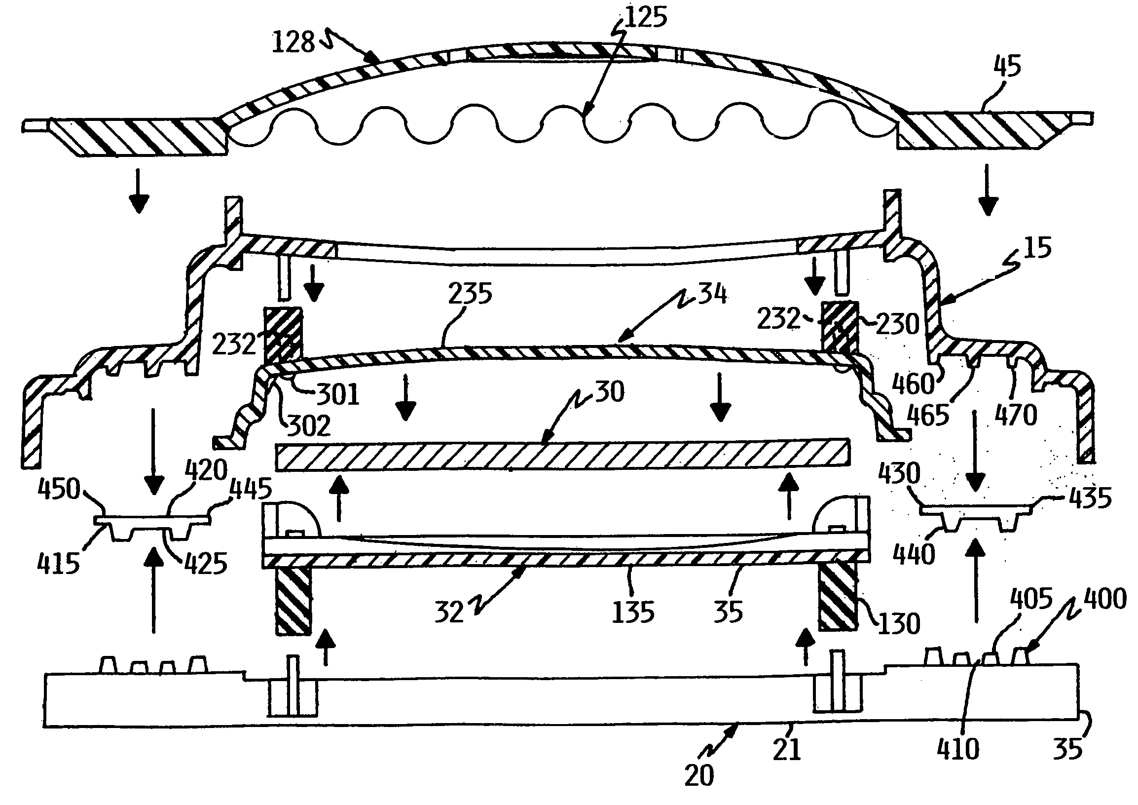
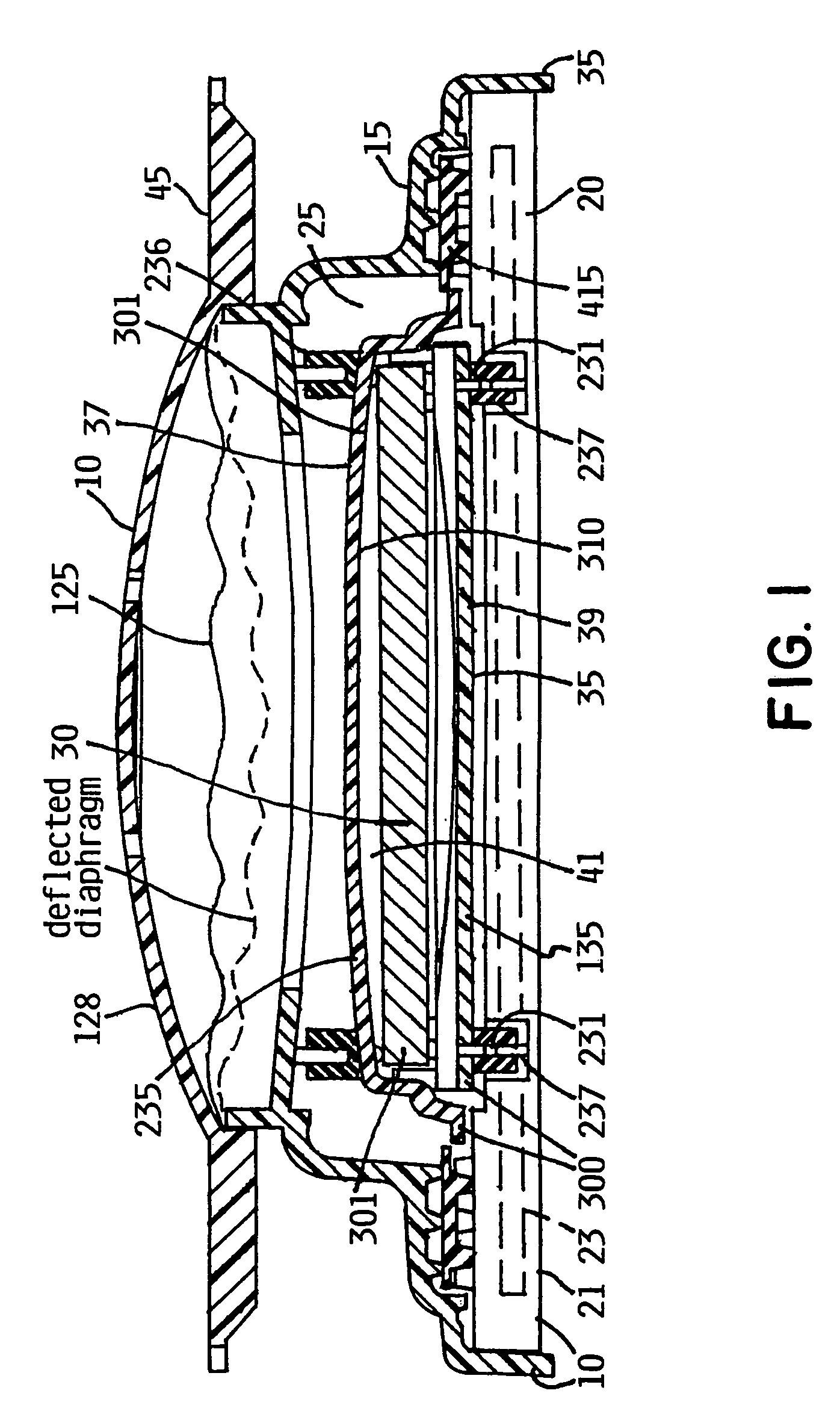
[0043]Referring now to FIG. 1, there is illustrated a reticle container 10 (...


PUM


Abstract

The present invention provides a reticle container that is equipped with a secondary container which houses the reticle and is housed in the primary container. The secondary container is held within the primary container with shock and vibration isolation members so that the secondary container has multiple degrees of freedom of motion within the primary container. The reticle is secured inside the secondary container such that shock and vibration transmission from the reticle container to the reticle is substantially attenuated.

Description

RELATED APPLICATIONS[0001]The present application claims the benefit of U.S. Provisional Application Ser. No. 60 / 657,616, filed Feb. 27, 2005, U.S. Provisional Application Ser. No. 60 / 657,355, filed Feb. 27, 2005, and U.S. Provisional Application Ser. No. 60 / 774,834, filed Feb. 18, 2006, which are included herein in their entirety by reference.FIELD OF THE INVENTION[0002]The invention relates to substrate carriers and in particular to processor carriers and shippers and in particular to reticle containers.BACKGROUND OF THE INVENTION[0003]Photolithography is one of the process steps commonly encountered in the processing of silicon wafers for semiconductor applications. In photolithography, a wafer surface with a deposit of silicon nitride is coated over with a light-sensitive liquid polymer or photoresist and then selectively exposed to a source of radiation using a template with a desired pattern. Typically, ultraviolet light is shone through or reflected off a surface of a mask or...

Claims


Application Information

Patent Timeline
Patent Type & Authority Patents(United States)
IPC IPC(8): B65D85/00
CPCG03F1/66G03F7/70741H01L21/67353H01L21/67386H01L21/67369H01L21/67376H01L21/67359B65D85/00H01L21/673B65D85/38
Inventor GREGERSON, BARRYHALBMAIER, DAVIDSUMNER, STEPHENWISEMAN, BRIANTIEBEN, ANTHONY MATHIUSSTRIKE, JUSTIN
Owner ENTEGRIS INC
Why Eureka
Try Eureka