
Motion transfer mechanism for transferring reciprocal motion to rotary motion and rider-propelled vehicle utilizing motion transfer mechanism

a technology of motion transfer mechanism and reciprocal motion, which is applied in the direction of interengaging clutches, cycles, gearing, etc., can solve the problems of lost motion and wasted energy, difficult for the rider to exert a constant propulsive force, and inefficiently do so. achieve the effect of simple and efficient manner

Inactive Publication Date: 2010-12-23
BEZERRA WILSON X +1
View PDF8 Cites 13 Cited by
  • Summary
  • Abstract
  • Description
  • Claims
  • Application Information

AI Technical Summary

Benefits of technology

[0011]It is an object of the present invention to provide a motion transfer mechanism for transferring reciprocal motion to rotary motion in a simple and efficient manner and which is particularly suited for rider-propelled vehicles.
[0012]It is another object of the present invention to provide a motion transfer mechanism wherein reciprocal motion applied to pivoted levers or crank arms is effectively transferred to rotary motion of a driven member without requiring the application of substantial force.
[0013]It is another object of the present invention to provide a motion transfer mechanism for transferring reciprocal motion to rotary motion to propel a rider-propelled vehicle, characterized by a smooth and uniform transmission of force independent of the speed of the vehicle.
[0014]It is another object of the present invention to provide a motion transfer mechanism for transferring reciprocal motion to rotary motion to propel a rider-propelled vehicle, in which the transmission of force and the mechanical advantage are improved to reduce the effort which must be expended by the rider.
[0015]It is still another object of the present invention to provide a motion transfer mechanism for transferring reciprocal motion to rotary motion, wherein reciprocal motion of a pair of pivotal levers or crank arms is transferred to rotary motion to propel a rider-propelled vehicle with efficient transfer of applied power and reduced resistance to power transfer.
[0016]It is yet another object of the present invention to provide an improved rider-propelled vehicle, such as a tricycle, that is easy to operate by persons having less than average agility or strength, such as the elderly, young children, and children with special needs.

Problems solved by technology

Although this circular peddling motion is effective in creating sufficient force to propel the vehicle forward, it does not do so efficiently.
The circular peddling motion required to propel the driven wheel of the conventional tricycle forward results in lost motion and wasted energy.
The driving force that propels the conventional tricycle is developed from the outward and / or downward extension of the rider's legs and feet (relative to the seating and pedal positions) along part of the circular path of travel of the pedals, and the circular path makes it difficult for the rider to exert a constant propulsive force.
As a result, the rider is not able to optimize the results of their energy expenditure which is especially significant during a long journey.
Additionally, the smoothness of operation of the tricycle is compromised since the transmission of force depends on the position of the pedals during their cycle of rotation, resulting in non-uniform transmission of force.
Since the non-uniformity of the force transmission is independent of the speed of the vehicle, the non-uniformity is especially pronounced at low speeds.
Another problem with the aforementioned conventional tricycles is that the pedals are driven in a circular motion with vertical and horizontal force components, thereby making the application of force to the pedals inefficient.
Therefore, the conventional tricycles, in which rotary motion of the pedals is converted to rotary motion of the driven wheel have the drawbacks of ineffective transmission of force, poor mechanical advantage, low power output and high resistance, and require the application of substantial force in order for the rider to propel the tricycle, particularly when starting up or accelerating.
When the rider of the conventional tricycle is a young child, he / she may not be able to ride the tricycle because his / her legs may be too short, he / she does not have any power to turn the pedals, and / or he / she cannot reach the pedal.
The current existing tricycles make it very difficult for a very young child to turn the pedals to propel the tricycle.
As a result, children tend to get tired of playing with it easily.
However, the transmission of the reciprocal motion of the levers to drive the rider-propelled vehicle has not been satisfactory.
As a consequence, such conventional rider-propelled vehicles have certain features which render them difficult or impractical to use by many persons, including persons having less than average agility or strength, such as the elderly, young children, and children with special needs.

Method used


Image

  • Motion transfer mechanism for transferring reciprocal motion to rotary motion and rider-propelled vehicle utilizing motion transfer mechanism
  • Motion transfer mechanism for transferring reciprocal motion to rotary motion and rider-propelled vehicle utilizing motion transfer mechanism
  • Motion transfer mechanism for transferring reciprocal motion to rotary motion and rider-propelled vehicle utilizing motion transfer mechanism

Examples


Embodiment Construction

[0039]While this invention is susceptible of embodiments in many different forms, this specification and the accompanying drawings disclose only a specific form as an example of the use of the invention. The invention is not intended to be limited to the embodiment so described, and the scope of the invention will be pointed out in the appended claims.

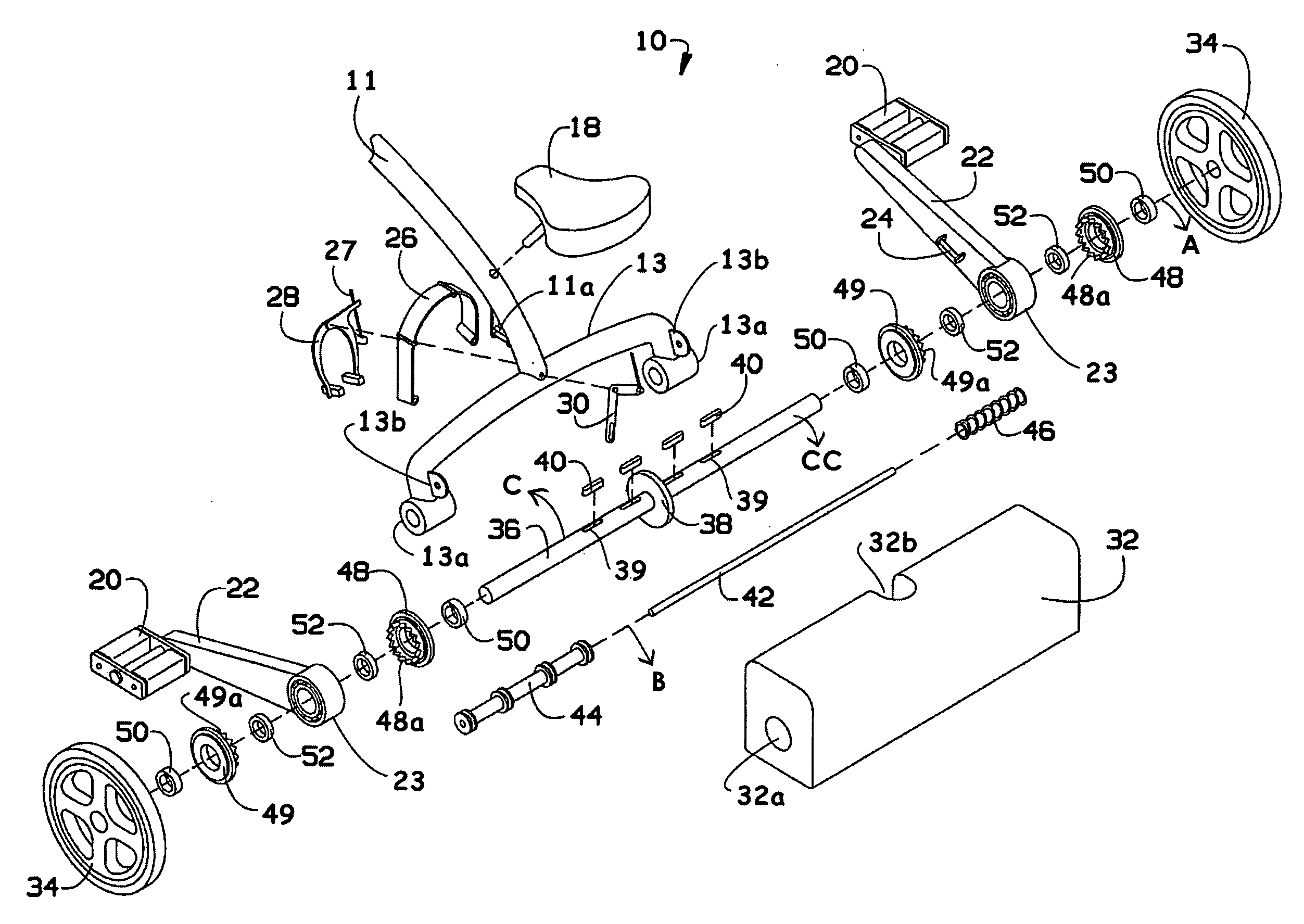
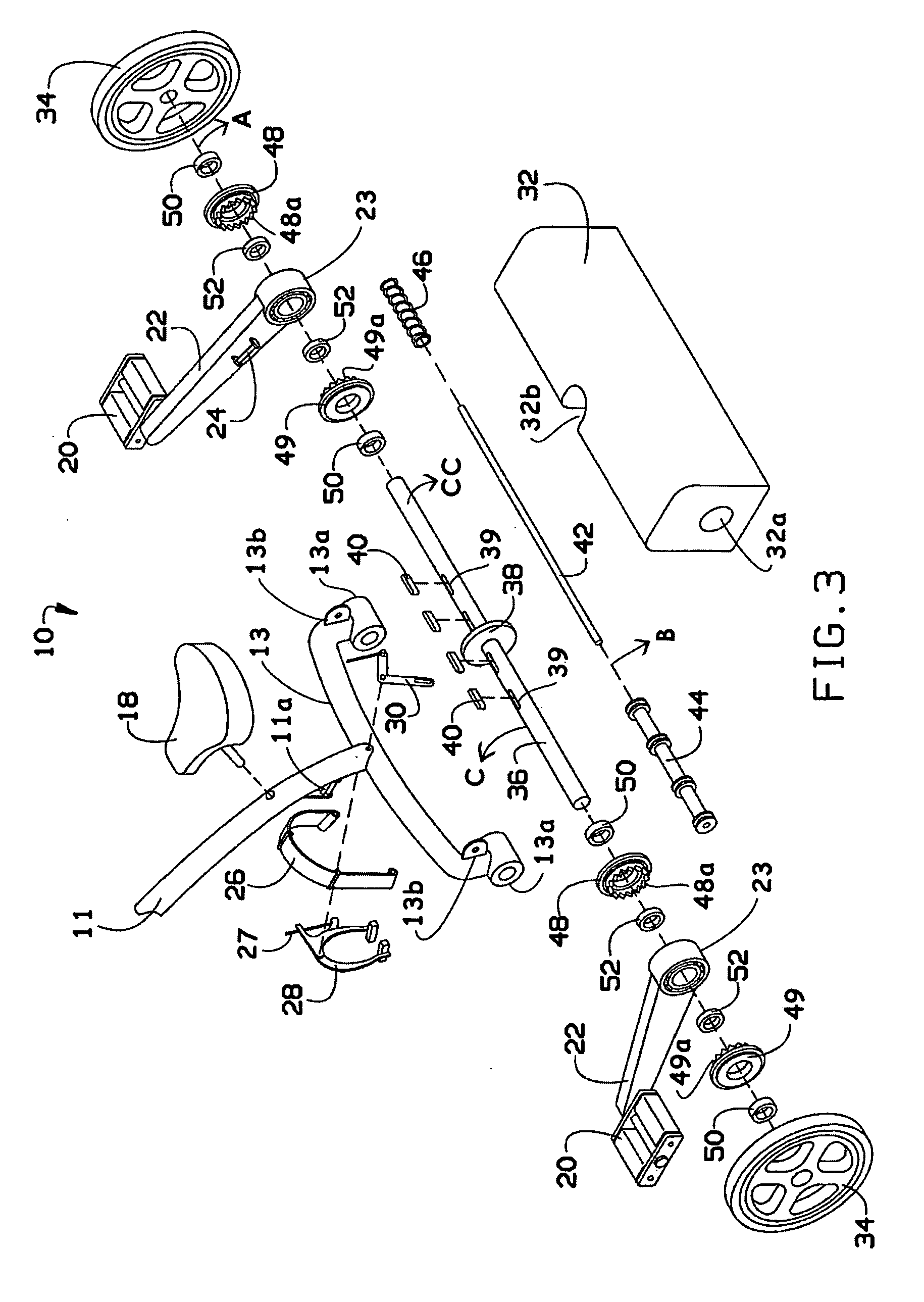
[0040]The preferred embodiment of the motion transfer mechanism according to the present invention is described below with a specific application to a rider-propelled vehicle, particularly a tricycle. However, it will be appreciated by those of ordinary skill in the art that the following preferred embodiment of the motion transfer mechanism is also particularly well adapted for other rider-propelled vehicles such as, for example, bicycles, paddle boats, hydrobikes, small aircraft, wheelchairs and skateboards. It will also be appreciated by those of ordinary skill in the art that the preferred embodiment described below is not limited ...


PUM


Abstract

A motion transfer mechanism for transferring reciprocal motion to rotary motion. The motion transfer mechanism comprises at least one driving member configured to undergo reciprocal motion about a first axis and at least one clutch housing integral with the at least one driving member and configured to undergo angular displacement about the first axis during reciprocal motion of the at least one driving member. A driven member supports the at least one clutch housing and is mounted to undergo rotary motion in a direction of rotation about the first axis. At least one unidirectional clutch mechanism is mounted on the driven member and is configured to engage the at least one clutch housing for effecting rotation of the driven member in the direction of rotation during reciprocal motion of the at least one driving member.

Description

CROSS-REFERENCE TO RELATED APPLICATIONS[0001]The present application for patent claims priority benefit of Provisional Application Ser. No. 61 / 187,863, filed Jun. 17, 2009. This provisional patent application is hereby expressly incorporated by reference herein in its entirety.BACKGROUND OF THE INVENTION[0002]1. Field of the Invention[0003]The present invention relates generally to motion transfer mechanisms and, more particularly, to a motion transfer mechanism for transferring reciprocal motion to rotary motion and which is particularly suited for rider-propelled vehicles.[0004]2. Background of the Invention[0005]Over the years, a wide variety of rider-propelled vehicles have been devised. Among the more popular rider-propelled vehicles are three-wheeled vehicles known as tricycles that include a frame, a front wheel and a pair of rear wheels carried on the frame, a seat for the operator, a steering handle to steer the tricycle, and rotary pedals for propelling the tricycle. Ordin...

Claims


Application Information

Patent Timeline
Patent Type & Authority Applications(United States)
IPC IPC(8): B62M1/04F16D41/00B62M1/24
CPCB62K9/02B62M1/30F16D11/10Y10T74/18056F16D41/30F16D47/04F16D41/12
Inventor BEZERRA, WILSON X.BEZERRA, SILVANA A.
Owner BEZERRA WILSON X
Features
  • Generate Ideas
  • Intellectual Property
  • Life Sciences
  • Materials
  • Tech Scout
  • Unparalleled Data Quality
  • Higher Quality Content
  • 60% Fewer Hallucinations
Learn More